The motor controller has small high speed switches which turn on and off thousands of times a second. The slow speed is obtained by using the 43uf capacitor purple p the medium speed is obtained by using the 21uf capacitor red r and the high speed is obtained by direct connection no capacitor.

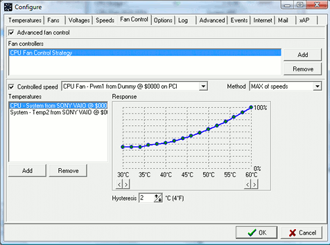
Computer Fan Control Wikipedia
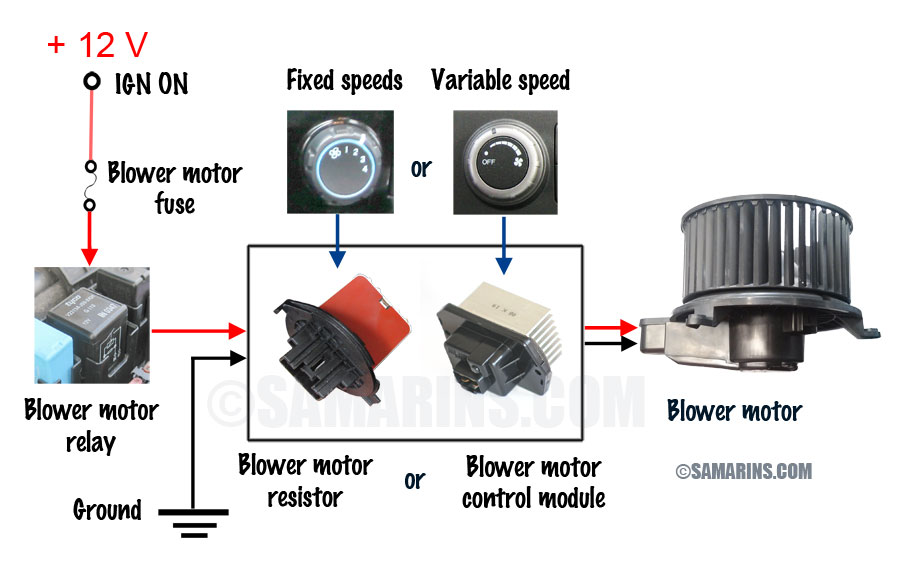
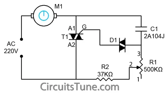
How do fan speed controllers work. Negative lipo connections. The greater the resistance higher is the voltage drop across it and that lowers the speed of the fan. Two basic types of speed controls exist for ceiling fans. Gnd reference of pwm signal. In short pwm operates like a switch which constantly cycles on and off thereby regulating the amount of power the fan or pump motor gains. I infer that the fan controller works by inserting a capacitance into the fans power supply circuit.
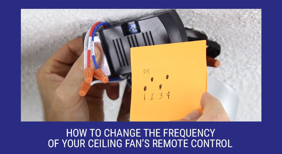
This is to give you the freedom of choice to have any type of switch plate you want. A series connection implies the resistance is in line with the fan. Components used in esc. How does a ceiling fan speed control work. By adjusting the duty cycle or switching frequency of the transistors the speed of the motor is changed. In order to control the fans speed.
Mechanical speed controls work by restricting the current the apparent change in voltage is only what you measure. In a lot of cases the whole plate is not included but rather only the 3 speed mechanism is supplied. Wall controls and controls on the unit itself. Positive lipo connection. This reduces the voltage drop across the fan and its speed to your desired level. They also need to be a good match to the motor.
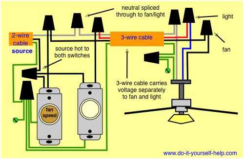
Majority of fans include a wall switch 3 speed dial that can be fitted into any standard switch plate. Solder jumper for altering the direction of rotation cwccw solder jumper for varying the type of. The wave is similar enough to actual ac to power the motor. Some of you probably already know the principle on which pulse width modulation pwm works but nevertheless we will explain how it actually controls the speed of a fan or a pump. Servo signal or input of the pwm signal. Together they create a stair step wave a wave that takes very small steps to emulate the curve of a real ac wave.
Each switch creates a small increase or decrease in voltage. An electronic speed control follows a speed reference signal derived from a throttle lever joystick or other manual input and varies the switching rate of a network of field effect transistors fets. An electric chopping device on the other hand only needs to be capable of handling the max power generally what will handle a lot will also handle a little except for some performance types that lack low speed control cutting in suddenly at about 14 power. Solder pads for the 3 bldc motor phases. May 23 2009 0445 pm 9. A ceiling fans wiring is integral when it comes to controlling its speed.
