Baldor single phase capacitor wiring reading industrial pdf. Each component ought to be placed and linked to different parts in particular manner.

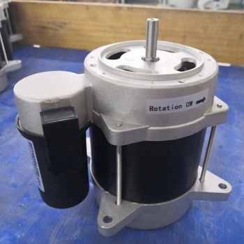
230v Single Phase Induction Motor Wiring Diagram View Single Phase Sok Motor Product Details From Suzhou Sok Micro Motor Manufacturing Co Ltd On
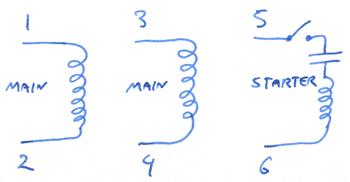
Wiring diagram for 230v single phase motor. A motor with a start and run capacitor and a start and run coil. It is important to point out from the phasor diagram that the phase difference between im and is is almost 80 degrees as against 30 degrees in a split phase induction motor. 240v motor wiring diagram single phase single switch wiring diagram 110 single circuit diagrams wire center u2022 rh casiaroc co. Single phase motor wiring diagram with capacitor baldor single phase motor wiring diagram with capacitor single phase fan motor wiring diagram with capacitor single phase motor connection diagram with capacitor every electrical arrangement is made up of various unique pieces. Baldor electric motor capacitor wiring wiring diagram pdf. Variety of baldor single phase 230v motor wiring diagram.
Single phase motors are used to power everything from fans to shop tools to air conditioners. Baldor industrial motor wiring diagram wiring schematic pdf. Run capacitor wiring diagram wiring diagram images gallery pdf. It is to be. Motor power hp transformer apparent power kva wire gauge awg distance from motor to transformer. Literally a circuit is the course that enables electrical energy to flow.
Fdl3732m product catalog baldor com pdf. The objective is the exact same. 8cd21 230v single phase capacitor wiring diagram digital pdf. This video will show you how to connect a single phase motor with two capacitors. Baldor wiring diagram single phase wiring diagram images pdf. Thus a capacitor start induction run motor produces a better rotating magnetic field than the split phase motors.
Baldor ac motor diagrams basic electrical wiring theory pdf. Click on the image to enlarge and then save it to your computer by right. Split phase motor dual voltage reversible rotation capacitor motor single phase wiring diagrams always use wiring diagram supplied on motor nameplate w2 cj2 ui vi wi w2 cj2 ui vi wi a cow voltage y high voltage z t4 til t12 10 til t4 t5 ali l2 t12 ti blu t2 wht t3org t4 yel t5 blk t6 gry t7 pnk direct on line dol motor starter direct on line dol motor starter 3 wiring of dol devices for 230v single phase with 230v coil wiring of additional start stop devices on dol devices for 400v 3. Recommended copper wire gage and transformer size for single phase 230 volts electrical motors. It is evident from the phasor diagram that the current through the starter winding is leads the voltage v by a small angle and the current through the main winding im lags the applied voltage. If not the arrangement wont work as it should be.
Residential power is usually in the form of 110 to 120 volts or 220 to 240 volts. Assortment of 240v motor wiring diagram single phase. Baldor single phase 230v motor wiring. An initial look at a circuit layout could be complex yet if you could check out a metro map you can check out schematics. Wiring diagram images detail. Baldor single phase 230v motor wiring diagram a newbie s overview to circuit diagrams.
Wiring a motor for 230 volts is the same as wiring for 220 or 240 volts. All wiring and electrical connections should comply with the national electrical code nec and local codes and practices. It reveals the parts of the circuit as streamlined shapes and the power and signal connections in between the gadgets. Circuit wiring single phase 230v electrical motors recommended copper wire gage and transformer size for single phase 230 volts electrical motors. Obtaining from point a to point b. A wiring diagram is a simplified conventional pictorial depiction of an electric circuit.
Baldor single phase 230v motor wiring diagram.


