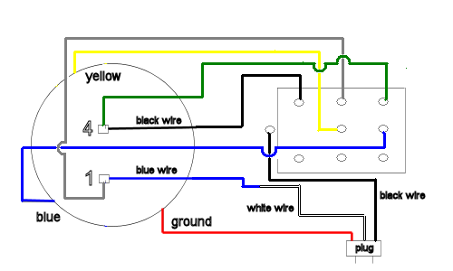
If not the arrangement wont work as it should be. This motor has two identical main windings arranged for either series or parallel connections.

3 Phase Motor Wiring Diagram For A C Nissan 7 Mareikekirsch De
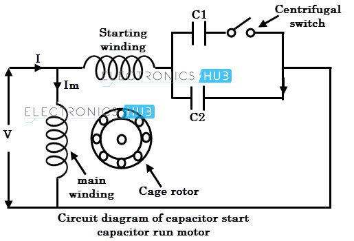
Single phase ac motor wiring. Every home workshop and vessel has them. Since there is such a wide variety of these motors it is impossible to describe all of them. Split phase single value capacitor electric motor dual voltage type. A single phase induction motor is similar to the three phase squirrel cage induction motor except there is single phase two windings instead of one three phase winding in 3 phase motors mounted on the stator and the cage winding rotor is placed inside the stator which freely rotates with the help of mounted bearings on the motor shaft. Each component ought to be placed and linked to different parts in particular manner. This video will show you how to connect a single phase motor with two capacitors.
Single phase motors are used to power everything from fans to shop tools to air conditioners. Starting winding is also known. The basic diagram view a shows a circle with two leads labeled t1 and t2. With the main windings connected in parallel the line voltage is usually 240. Single phase induction motors are used in residential applications for ac motor appliances in single or multiple dwellings. Single phase motor wiring diagram with capacitor baldor single phase motor wiring diagram with capacitor single phase fan motor wiring diagram with capacitor single phase motor connection diagram with capacitor every electrical arrangement is made up of various unique pieces.
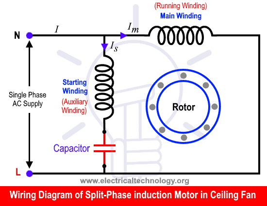
Generally the ceiling fan motors are split phase single phase ac motors. Residential power is usually in the form of 110 to 120 volts or 220 to 240 volts. Single phase ac motors are the most common motors built. A direct current dc single phase motor starts turning automatically once electricity is connected but an alternating current ac single phase motor needs a capacitor to initiate rotation. A motor with a start and run capacitor and a start and run coil. This chapter will describe the most common types found on army watercraftfigure 17 1 shows the basic schematic diagrams for the single phase motors.
When the main windings are connected in series 120 volts is used. There are two winding inside the ceiling fan known as starting winding and running winding. A single phase induction motor is an electric motor that operates on a single waveform of alternating current. Wiring a motor for 230 volts is the same as wiring for 220 or 240 volts. Just as in the three phase motor diagram the motor shows the power supply. This is because ac current alternates about 60 times a second so without a capacitor the motor would simple vibrate rather than rotate.
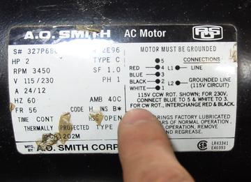
Be sure you have selected the correct wiring configuration before you begin wiring. Some motors allow both 120 volt and 240 volt wiring by providing a combination of wires for doing so.
