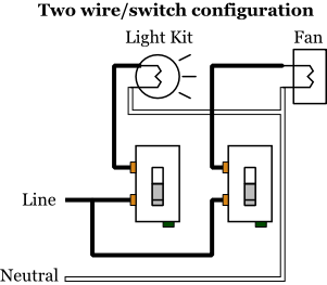
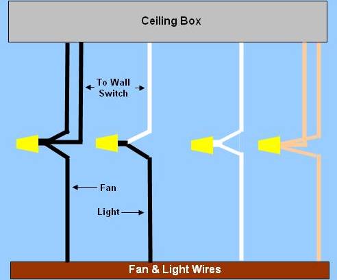
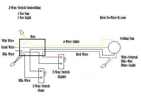
At the outlets each is wired using a pigtail splice to make the hot and neutral connections. Switched lines and neutral connect to a 3 wire cable that travels to the lightfan outlet box in the ceiling.

Wiring Diagram For A Bathroom Fan Diagram Base Website
Fan wiring diagram switch. Assortment of wiring diagram 3 way switch ceiling fan and light. Connect white wires together. February 28 2019 by larry a. Connect the red wire to the screw in switch 2. This wiring diagram illustrates the connections for a ceiling fan and light with two switches a speed controller for the fan and a dimmer for the lights. Connect the black wire to the screw located in swith 1.
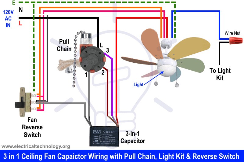
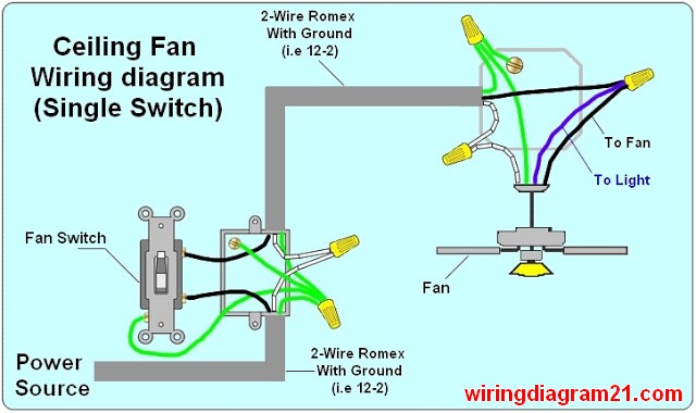
Black wire in terminal 3 and terminal number l 1 2 3 is in counterclockwise order. This wiring method is used when the power source is from the switch and one wants to control the fan and light from that single switch. Ceiling fan switch wiring diagram 2 line voltage enters the switch outlet box and the line wire connects to each switch. The source for the circuit is at the switch and 2 wire cable runs to each receptacle outlet. Injunction of 2 wires is generally indicated by black dot at the intersection of two lines. The source is at the switches and the input of each is spliced to the black source wire with a wire nut.
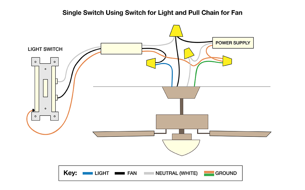
This diagram shows the wiring for multiple switched outlets on one switch. Ceiling fan wiring diagram with single switch. Wu pin ljy 280a 4 hole fan switch. Black wire in terminal 3 and terminal number l 1 2 3 is in counterclockwise order. Defond 4 hole fan switch. It shows the elements of the circuit as streamlined forms and also the power and also signal connections in between the devices.
Sometimes the wires will cross. The hot source is connected directly to the bottom terminal on the switch. Black wire in terminal 3 and terminal number l 1 2 3 is in. In the switch box. Here is a picture gallery about ceiling fan reverse switch wiring diagram complete with the description of the image please find the image you need. Connect black fan wire to the black ceiling wire.
Shine top ls 102 fan switch. It reveals the elements of the circuit as simplified shapes and the power and signal connections between the tools. Wellborn collection of 4 wire ceiling fan switch wiring diagram. A wiring diagram is a streamlined standard pictorial depiction of an electrical circuit. From there two wires run to the ceiling fan. Connect the blue wire to the red wire.
Split the incoming hot wire into a y and connect it to a terminal on each switch. Wiring diagram for multiple switched outlets. Minka aire concept ii ceiling fan hard wiring help please with ceiling fan reverse switch wiring diagram image size 600 x 356 px and to view image details please click the image. According to earlier the traces in a hampton bay 3 speed ceiling fan switch wiring diagram represents wires. The fan control switch usually connects to the black wire and the light kit switch to the red wire of the 3 way cable. However it does not imply link between the wires.
From the switches 3 wire cable runs to the ceiling outlet box. A wiring diagram is a streamlined conventional photographic depiction of an electrical circuit.


