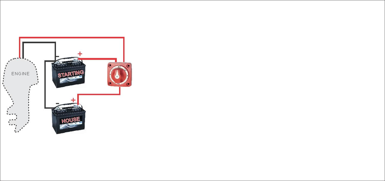
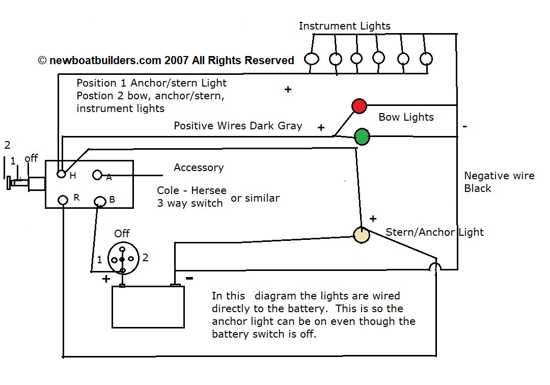
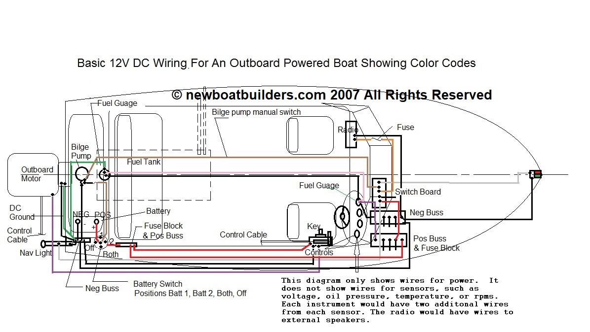
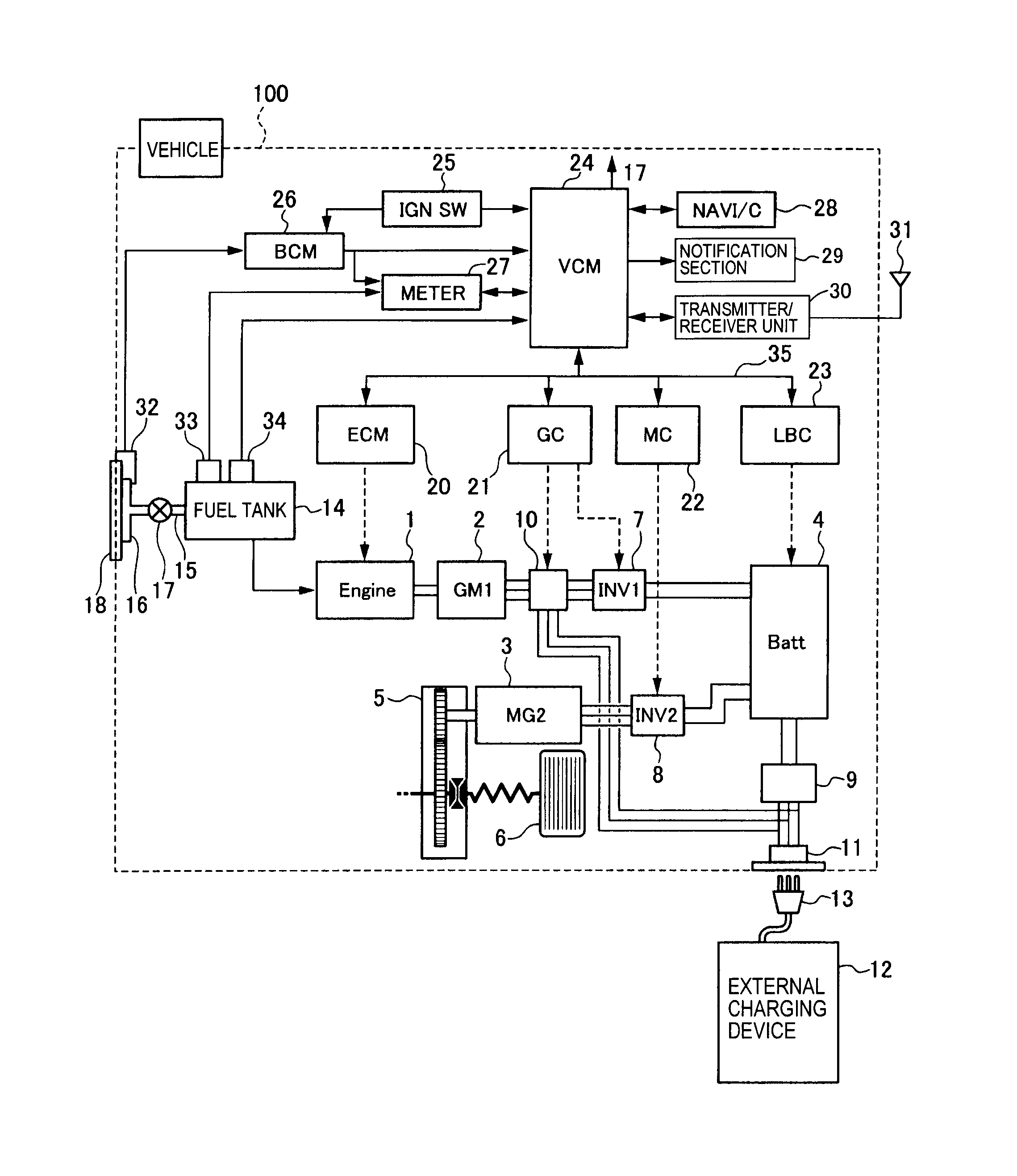
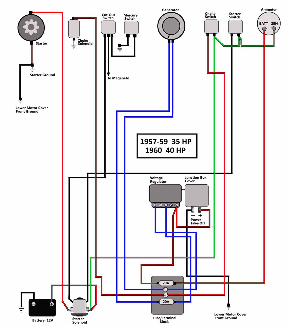
The wires may follow a seemingly unusual path but the system works. Click on the image to enlarge and then save it to your computer by right.

Wiring Diagram For Boat Fuel Gauge Diagram Base Website Fuel
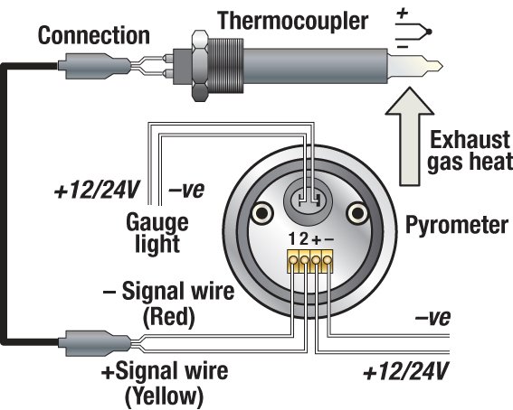
Wiring boat gauges diagram. Wiring a fuel gauge is much the same as wiring any other gauge on your boat. Boats and maintenance 10 basic rules for wiring a boat. One wire comes from the ignition to the instrument one wire comes from the sensor to the instrument one wire comes to the instrument light and one wire from the instrument goes to the boats common ground. Items you will need. Fishing bait fishing lures. Slide anchor box anchors shop now.
Every problem cannot be solved with this checklist but it will give you a good starting place. Assortment of boat ignition switch wiring diagram. Unsubscribe from tiny boat nation. It shows the parts of the circuit as simplified shapes and the power as well as signal links between the devices. For example a trolling motor on a 20 foot boat should have 4 or 6 gauge wire for best battery utilization. A few notes before we start.
You may not always see our instruments but with some of the most sophisticated vehicle information and instrumentation systems in the industry and a range of products that are rugged. Is it no longer both wires lead to the back of the fuel gauge. Variety of marine fuel gauge wiring diagram. The vast majority of recreational boats in service today are still using analogue instrumentation systems. In this guide well stick with the 12vdc power distributions systems as opposed to engine or gauge wiring. Super easy boat wiring and electrical diagrams step by step tutorial tiny boat nation.
Fish finders sounders sonar. Ladders steps platforms. Boat ignition switch wiring diagram mercury marine ignition switch wiring diagram elegant. Fishing rod holders storage racks. Too much current can heat up the wiring to the point of starting a fire. Fishing rod reel combos.
I recently provided an answer to a. Boat fuel tank gauge wiring diagram wiring diagram is a simplified standard pictorial representation of an electrical circuit. Wiring diagram images detail. Disconnect your boats. A wiring diagram is a simplified standard pictorial depiction of an electrical circuit. It shows the components of the circuit as simplified shapes and the power and signal links surrounded by the devices.
Study schematics never be afraid to attempt the job and if necessary enlist expert help in the form of a reputable dealer or manufacturer and you can cut the down time significantly. Fishing tools tackle boxes. Dock storage protection. Boat owners should never cut corners on wiring jobs. More modern digital nmea networked and multifunction gauges may be all the buzz but the reality is that most boats are still equipped with the same analogue set ups that have been in use for decades. Voltage does not.
The insides of instrument panels can get a little crowded but untangling it is all a matter of circuits senders and wire colors. The back of the unitfind great deals on ebay for faria marine fuel gauge. Positive wires are red in our guide your boat may have other colors negative wires are black or may be yellow on your boat current is measured in amps a potential difference is measured in volts v current flows through the wires like water through a pipe.
