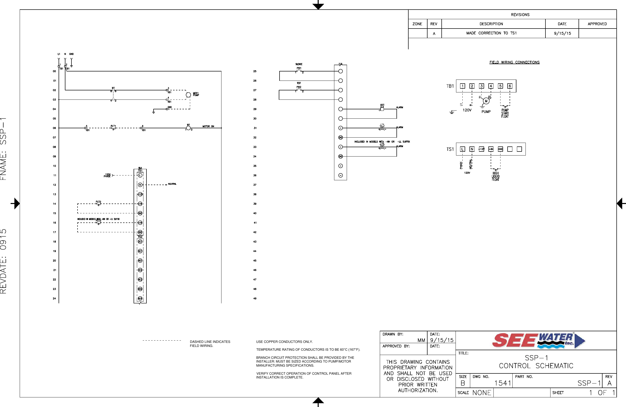
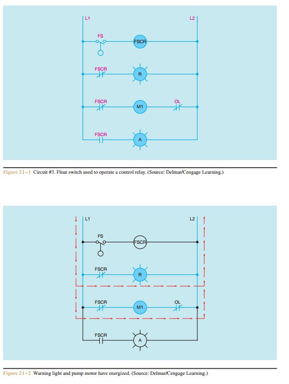
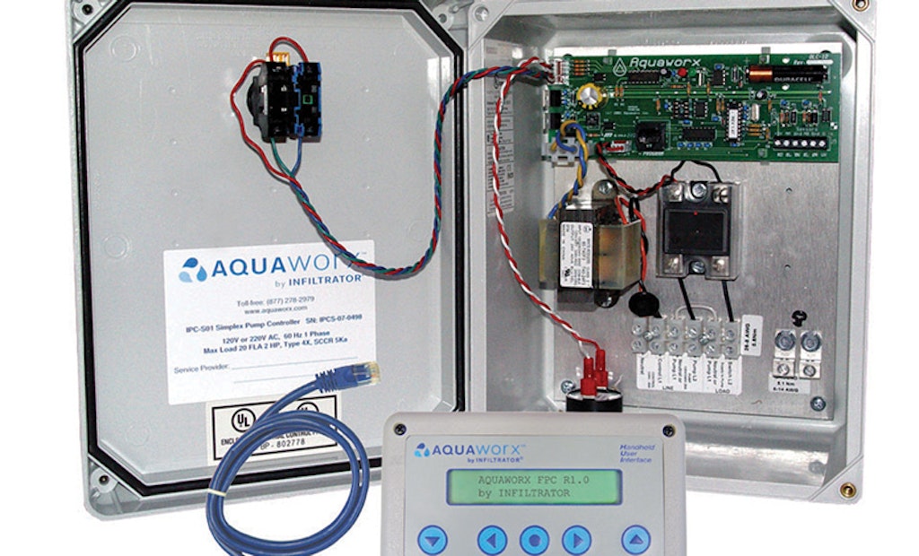
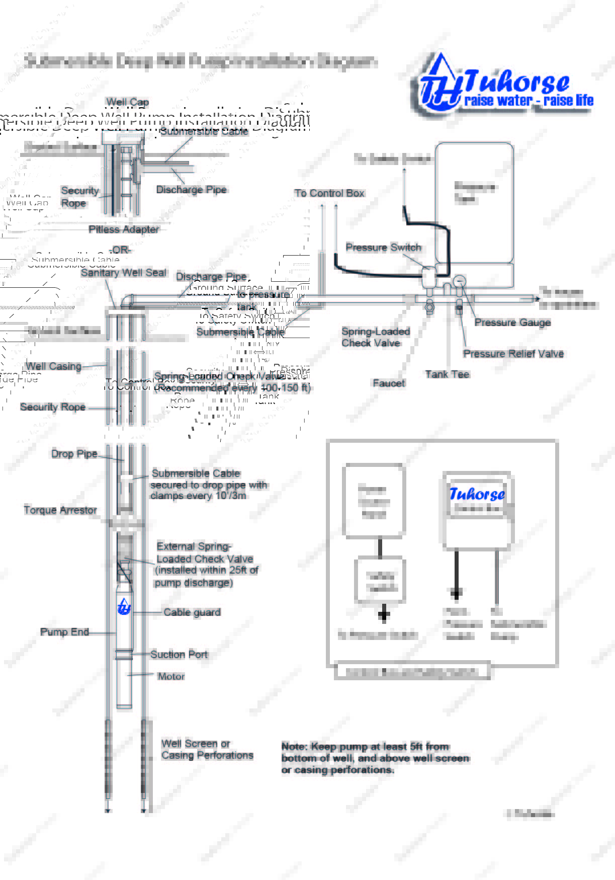
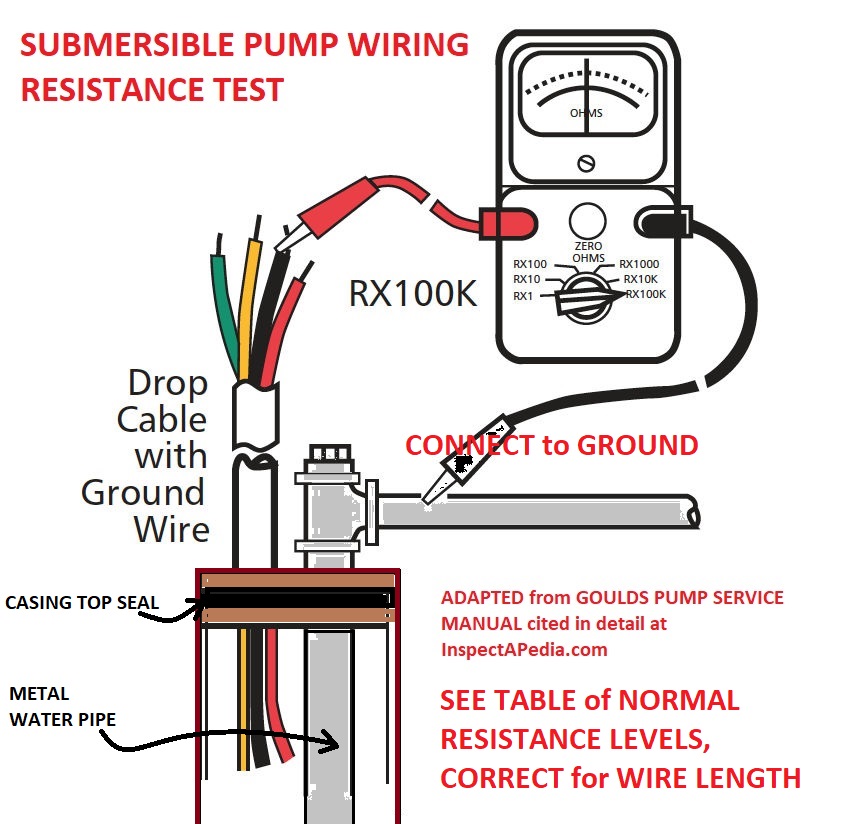
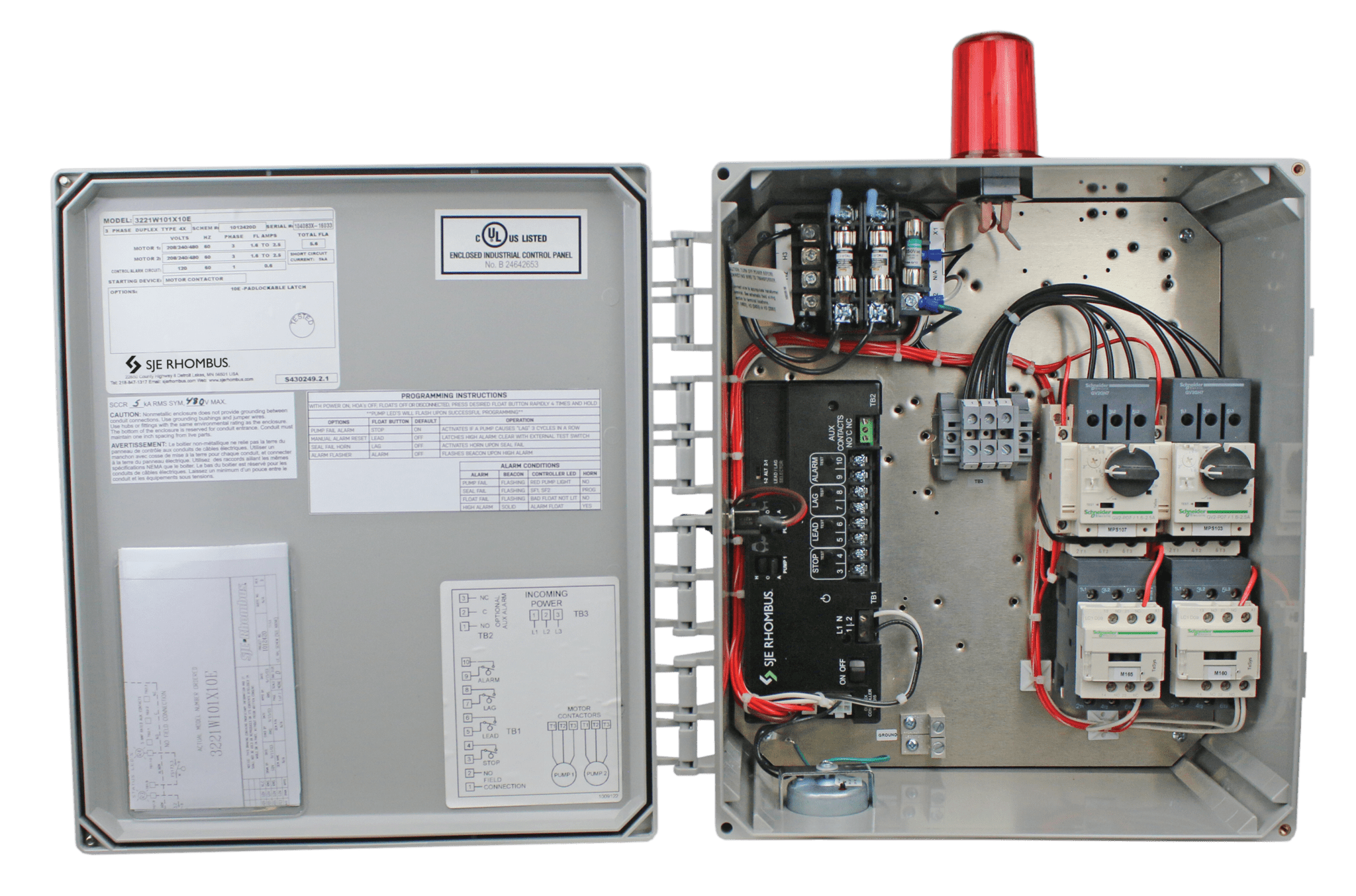
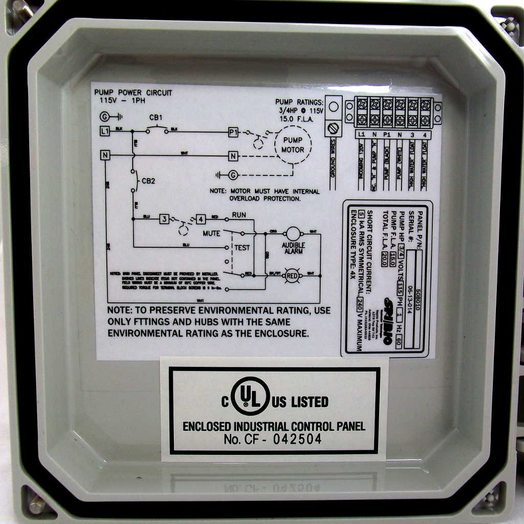
In the last video in this series we went over a 3 phase pump panel and how a pump is controlled both in auto mode as well as hand mode. In this video i have presentation about submersible pump control wiring diagram submersible pump box control wiring diagram no nc auxiliary contact working procedure.

Aim Manual Page 54 Single Phase Motors And Controls
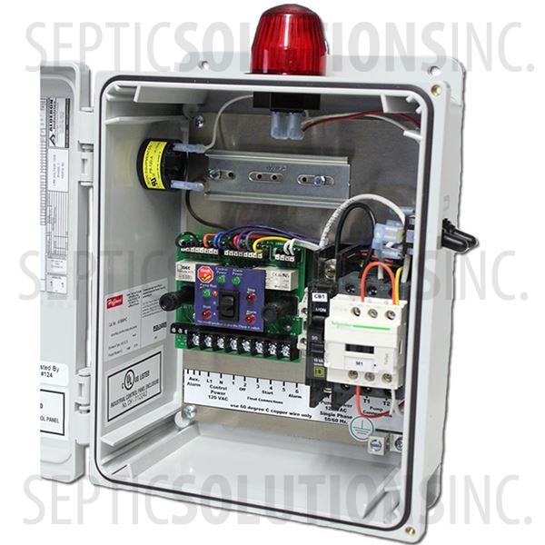
Water pump control panel wiring diagram. The wiring connection of submersible pump control box is very simple. The typical elements in a wiring diagram are ground power supply wire as well as connection output tools switches resistors reasoning gateway lights etc. Water pump control panel wiring diagram how to connect float switch to 3 phase pump best float switch for water tank 3 float septic system wiring diagram house wiring bangla diagram switch. To read a wiring diagram initially you have to recognize just what essential aspects are consisted of in a wiring diagram and also which photographic icons are used to represent them. How does no nc normally. In auto mode the pump will start using a standard float.
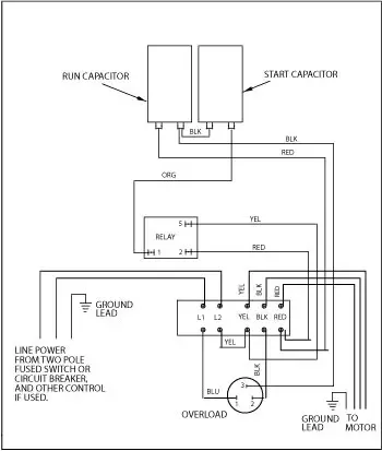
Install social plugin that has its own shortcode and add it to theme options socials login via social network field. Here is the complete guide step by step. A list of electrical icons as well as descriptions can be discovered on the electric sign page. Single phase submersible pump control box wiring diagram 3 wire submersible pump wiring diagram in submersible pump control box we use a capacitor a resit able thermal overload and dpst switch double pole single throw.

