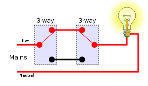
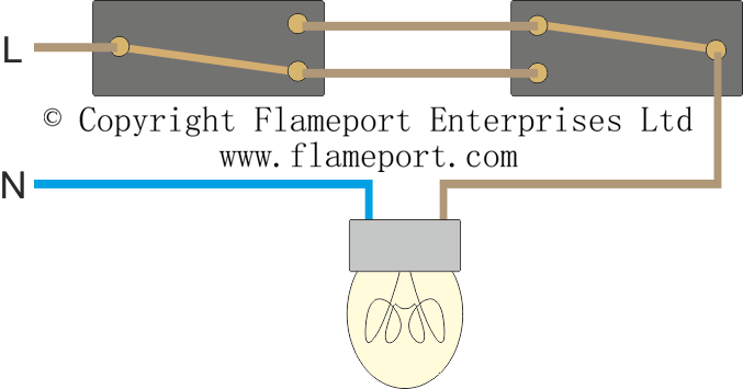
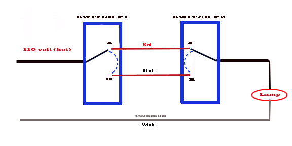
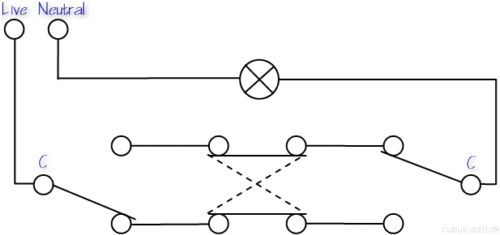
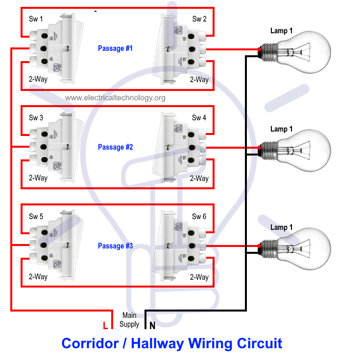
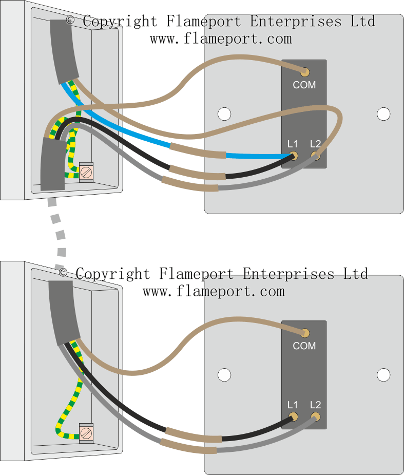
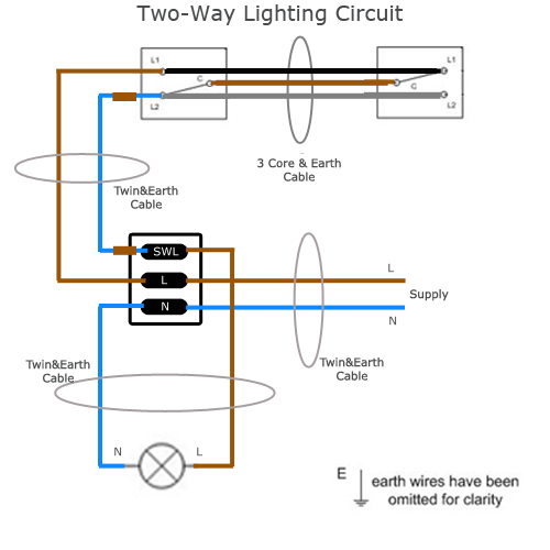
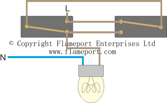
In this diagram two 3 way switches control a wall receptacle outlet that may be used to control a lamp from two entrances to a room. 3 way switched outlet wiring.

Resources
Two way switch circuit diagram. Uccn1004 lecture 5 routing in computer networks part 2 avocado 224 watching live now in shadow a modern odyssey animated short film duration. A 2 way switch wiring diagram with power feed from the switch light. 3 way light switching new cable colours 3 way light switch old cable colours 3 way light switch using a two wire control. The electricity flows from the hot wire black through the 2 way switch shown in off position and then to the light and returns through the neutral wire white. The power source comes from the fixture and then connects to the power terminal. This circuit is wired the same way as the 3 way lights at this link.
As you can see in the schematic diagram of 2 way switch circuit below the common of both the switches are short circuited. Three wire cable runs between the switches and the outlet. Pin1 of both the switches are connected with the phase or live wire and pin2 of both the switches are connected with the one end of the lamp. The other end of the lamp is connected with neutral line of ac power supply. Lets assume the load you are controlling is a light. 2 way switch 3 wire system old cable colours 2 way switch two wire control three way switching.
This is a completed circuit. You will see that there is a hot wire that is then spliced through a switch and that then goes to the hot terminal of the light. Before you start safety first. By wiring a 2 way switch the circuit below shows the basic concept of electricity flow to the load.

