I simply want to install the ge 15070 switch into the wall box so she can set the timer to control the outdoor lights. It reveals the parts of the circuit as streamlined shapes and the power as well as signal links between the tools.

Cs 5302 Cooper Wiring Diagram Single Switch Wiring Diagram
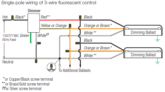
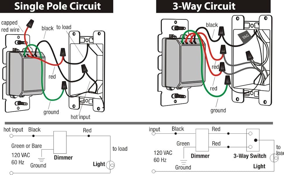
Single pole dimmer switch wiring diagram. Installation is a simple matter of connecting the hot wire leads to the hot circuit wiresone of which is entering the box from the power source the other leading to the light fixture. Assortment of single pole dimmer switch wiring diagram. Green dimmer ground lead to green or bare copper wire in wall box. Click on the image to enlarge and then save it to your computer by right clicking on the image. Black dimmer lead to any wall box wire removed from old switch. I know the red wire goes to the indoor light fixture.
Circuitry representations are made up of two things. Screw wire nuts on clockwise making sure no bare conductors show below the wire connectors. Red dimmer lead without insulating label to remaining wall box wire. If the switch youre replacing is the only switch controlling the light buy a standard single pole dimmer. Wiring a single pole light switch here a single pole switch controls the power to a light fixture. Single pole dimmer switch wiring diagram dimmer switches electrical 101 wiring diagram collection leviton 3 way switch wiring diagram inspirational 3 way dimmer whats wiring diagram.
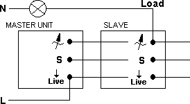
Single pole dimmer switch wiring diagram wiring diagram dual light switch 2019 2 lights 2 switches diagram unique wiring a light fitting diagram 0d. Secure each connector with electrical tape. In the diagram below a 2 wire nm cable supplies power from the panel to the dimmer boxthe black line wire connects to the common terminal of the 3 way dimmera 3 wire nm connects the travelers of the dimmer to the travelers of the 3 way switchtraveler wires are interchangeable on each switch. A wiring diagram is a kind of schematic which makes use of abstract photographic signs to reveal all the interconnections of parts in a system. The single pole switch currently in the wall has the black wire from the load pig tailed and the red wire from the line goes to the other terminal on the single pole switch. Wiring diagram for light switch with dimmer 2018 wiring diagram for wiring diagram dual light switch.
Traditional single pole dimmer switches like standard switches generally have just two hot wires and a ground wire with no neutral wire connection. Icons that stand for the components in the circuit as well as lines that stand for the connections between. But you wont be able to dim the lights from every switch location unless you buy a set of special dimmers with advanced electronics and install one at each switch location. Step 4 connect wires per wiring diagram as follows. Save money tv 14421 views. Remaining red dimmer lead should have red insulation label.
The source hot wire is connected to a switch terminal and the other terminal is connected to the black cable wire. If the light can be switched on and off from two or more switches buy a three way dimmer switch. A wiring diagram is a simplified conventional photographic depiction of an electrical circuit. The ge 15070 contains 1 black wire line 1 red wire load and 1 green wire ground. How to replace a standard switch with a dimmer switch for dummies duration. Variety of lutron single pole dimmer switch wiring diagram.
The source is at the switch and 2 wire cable runs from there to the light. Dimmer switch single pole wiring save money tv duration.


