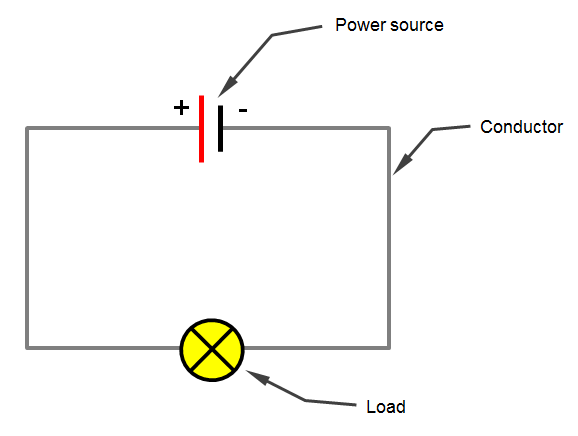
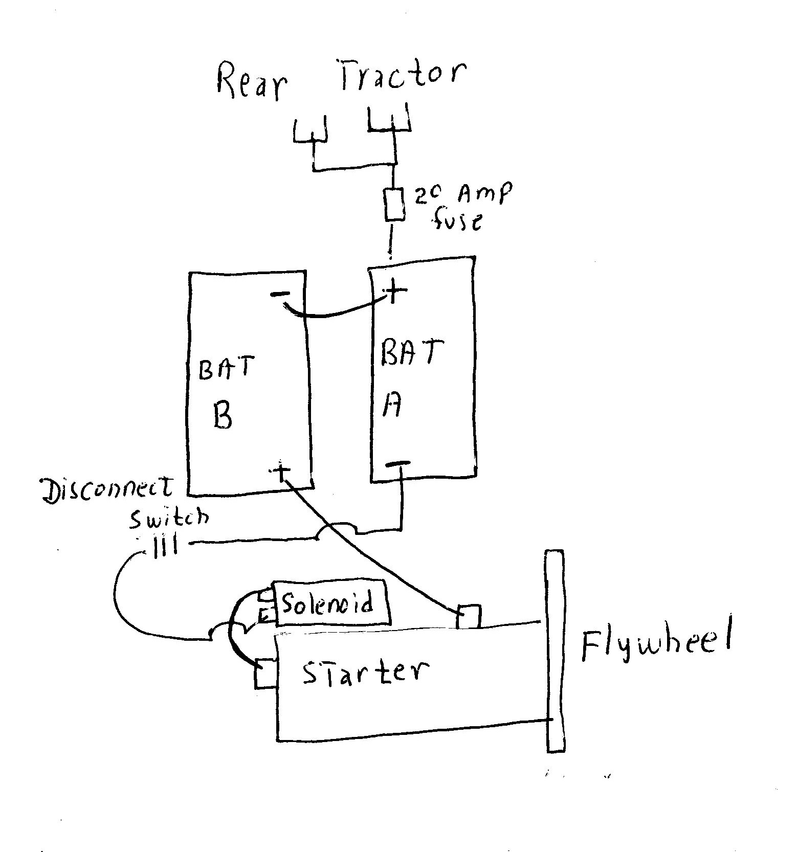
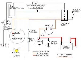
There is a really basic 12 volt trailer wiring diagram. If you do or plan to do any type of off grid camping boondocking then a 6v battery bank system is a superior choice over a single 12v battery.
Yesterday S Tractors Step By Step 12 Volt Conversion
Simple 12 volt wiring diagram. Variety of 12 volt solenoid wiring diagram. A wiring diagram is a simplified traditional pictorial depiction of an electrical circuit. Otherwise the structure wont function as it ought to be. Always check your vehicles owner manual to determine the voltage supply to your horn assembly before attempting to install a six volt horn. It shows the components of the circuit as simplified shapes and the gift and signal friends amongst the devices. Simple 12 volt battery charger circuit diagram designed by using few easily available components and this circuit is suitable for different types of batteries needs 12 volt.
Basic 12 volt wiring diagram wiring diagram is a simplified pleasing pictorial representation of an electrical circuit. It reveals the components of the circuit as simplified shapes and also the power and signal connections in between the tools. My question is many of the devices came with much smaller wire between 18 and 22 gauge that i am supposed to connect the 12 gauge wire to using butt connectors. The sideways movement simple campervan wiring diagram series part 2 charging 6 volt batteries in series with 12 volt charger. This type of connector is great for customer trailers. This circuit is designed to provide charging current upto 3 amps and this circuit dont have reverse polarity protection or over current protection so kindly test this circuit before stepping into battery charging.
12 volt horn wiring diagram see more about 12 volt horn wiring diagram 12 volt horn relay wiring diagram 12 volt horn wiring diagram. It is the 4 pin connector. It should not be carrying significant loads throughout the journey. I am getting ready to install a variety of 12 volt devices led lights submersible water pump etc and am using 12 awg wire for all applications just to be safe. The following basic wiring diagrams show how batteries battery switches and automatic charging relays are wired together from a simple single battery single engine configuration to a two engine one generator and four battery bank system. Does this difference in wire size matter.
Each part should be placed and connected with other parts in particular manner. Or should i forget using the 12 awg and use the same gauge wire extending from the device to run to my fuse block. A wiring diagram is a streamlined standard pictorial representation of an electrical circuit. A single battery tray two battery trays. Originally developed for high volume professional boat builders where quality assurance is never negotiable our snap together marine electrical systems offer a simple and safe alternative to previously complicated. A 6v battery bank charging system will give you added amp hours and increased life cycles.
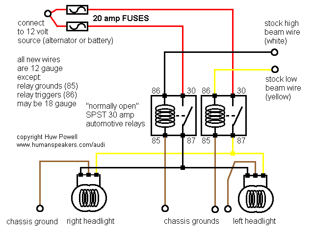
The switch only controls the relay. Here is an. Basic 12 volt boat wiring diagram 12 volt marine wiring diagram basic 12 volt boat wiring diagram every electrical arrangement is composed of various unique components. Using a 30 amp spdt relay connect terminal 87 to constant 12 volts positive with a fuse rated to the sum of the additional accessories youve added and the components you need to turn on. By charging 6 volt batteries in series with a 12 volt charger you allow your off grid electrical the true capacity it needs. You can use this circuit to charge 12v sla battery or 12v gel cell battery and so on.
It reveals the parts of the circuit as streamlined forms and the power as well as signal links between the devices. Assortment of 12 volt relay wiring diagram.
