Please choose a year from the menu at left to start your search. Otherwise the structure will not work as it ought to be.

Challenger On Rv Battery Wiring Diagram H1 Wiring Diagram
Rv battery wiring schematics. Diy wiring diagrams for 100w 200w 300w 400w 600w 800w kits. This guide even consists of ideas for additional supplies that you may require in order to end your assignments. A 12 volt dc electrical system and a 120 volt ac system. Solar calculator for rv or camper van conversions. Welcome to winnebago industries wiring diagrams. Each part should be set and connected with different parts in specific manner.
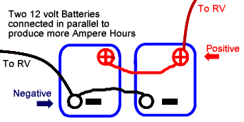
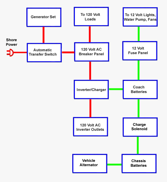
1 the ground wire for your battery and the ground wire from your tow connector should both be firmly connected to your campers chassis and the connections should not be rusty or loose. Use the rv electrical diagram we made below to get an understanding of what powers what and to learn how an rv electrical system works. Forest river wiring diagram forest river cardinal wiring diagram forest river cherokee wiring diagram forest river fr3 wiring diagram every electric structure is made up of various different components. One rv two electrical systems. Since rv circuits operate on 12 volts an rver who chooses to use golf car batteries will need two of them connected in series. Just as the individual cells are connected in series.
6 cells x 25 volts 126 volts. Forest river battery wiring diagram wiring diagram forest river wiring diagram wiring diagram also gives helpful ideas for tasks which may need some extra equipment. Types of rv electricity there are 2 main types of sources of rv electricity within your rv 12 volt dc and 120 volt ac same as 110 volt just like your stick brick for our purposes. The larger cells in the 6 volt battery allow it to provide electricity longer while maintaining a usable voltage and that is partly why many rvers choose to use them. 2 the hot wire for your running lights of your camper should be wired to the connections shown on a standard wiring chart for the specific type of connector. Rv electrical diagram wiring schematic understanding you campers electrical wiring can be very confusing.
Below is a rv electric wiring diagram or schematic including the converter and inverter for a generic rv. Your rv has two separate electrical systems. To wire the battery isolation solenoid you will need to splice the side terminals inline with the 7 way power wire attach a wire that is powered when the ignition is turned on to the small post on the front of the isolator and then mount the isolator to a portion of the vehicle that is grounded to the vehicle frame. The 12 volt system is powered by a battery or in some cases multiple batteries and it powers things such as the start up on your water heater furnace and refrigerator plus most of the lights in your rvs living space your water pump your carbon. Product list and cost of components.


