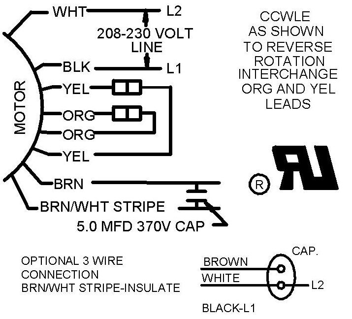
Shaded pole electric motor. The diagram depicts a reversible type that has two stator windings displaced as indicated.
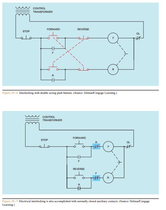
Forward Re Verse Control Developing A Wiring Diagram And
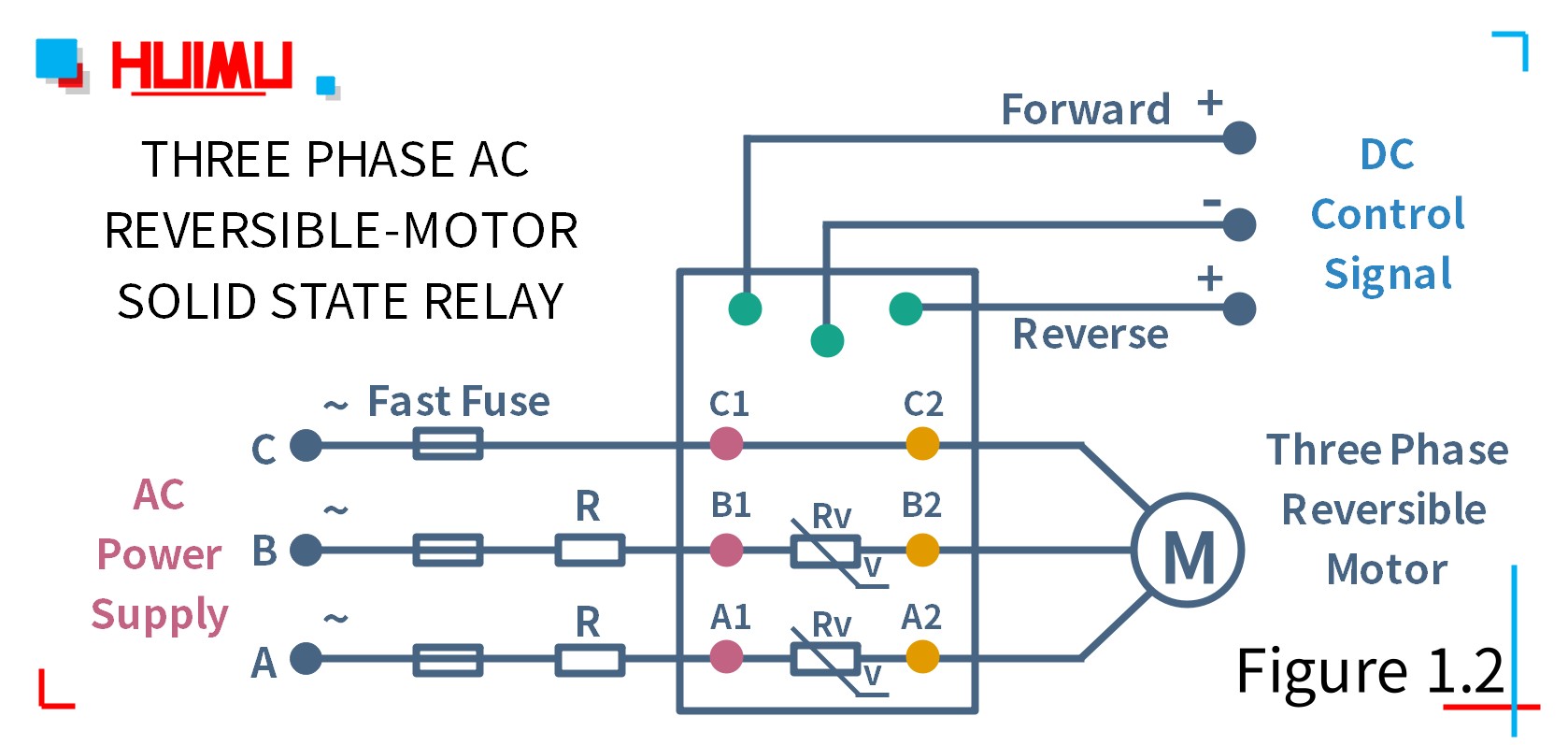
Reversible ac motor wiring diagram. Connect wires refer to the wiring diagram no4 picture 2. To reverse a dc motor the control device changes the direction of current flow in the motors armature. But for single phase ac motors the magnetic field only alternates back and forth. Assortment of electric motor reversing switch wiring diagram. Reversal of the motor is accomplished by interchanging the field winding connections. It shows the components of the circuit as streamlined shapes and the power as well as signal links in between the devices.
A wiring diagram is a streamlined standard photographic representation of an electrical circuit. Identify the correct capacitor value to be used with the ac motorgearmotor. Do not reverse positive and negative power loads. Variety of single phase motor wiring diagram forward reverse. Ill dispense with the background issues unless you really want to hear the story and post my wiring diagram both for checking and for a better way to do it. Motor control circuits use various control devices to change the direction in which a motor rotates.
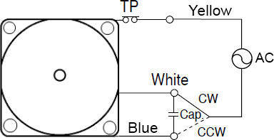
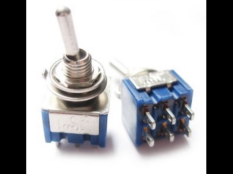
Theres so many switch types and incomplete switch and motor information that its difficult to reach a solid conclusion for a wiring. In order to reverse the direction of an ac motor the magnetic fields must be altered to provoke movement in the opposite direction. Reversing motor circuits provides a comprehensive overview of the various means used to reverse electric motors. A wiring diagram is a simplified conventional pictorial representation of an electrical circuit. Reversing a split phase motor in this split phase motor the main winding label m is connected directly to 60 hz ac power while the other winding label o is wired in series with a capacitor c. Some trickery is needed to create a rotating field.
This will damage the controller 1. Bodine gearmotor stock model 0670 type 42r 5n. Instructions for wiring or reversing a 4 wire ac gearmotor or motor. Bodine stock motors and gearmotors will have black blue black yellow blue yellow motor leads and a green yellow ground lead. The led indicates the power up and the speed of motor package includes. Turn on the power and adjust the potentiometer 3.
Reversing circuits typically use reversing starters but they may also use drum switches limit switches and programmable logic controllers. 3ø wiring diagrams 1ø wiring diagrams diagram er9 m 3 1 5 9 3 7 11 low speed high speed u1 v1 w1 w2 u2 v2 tk tk thermal overloads two speed stardelta motor switch m 3 0 10v 20v 415v ac 4 20ma outp uts diagram ic2 m 1 240v ac 0 10v outp ut diagram ic3 m 1 0 10v 4 20ma 240v ac outp uts these diagrams are current at the time of publication. Before you attempting to wire the controller make sure power is off. To reverse an ac motor the. It reveals the components of the circuit as simplified forms as well as the power as well as signal links in between the tools. Identify the wire colors and confirm that you have a 4 wire reversible psc permanent split capacitor motor or gearmotor.
Reversing an ac motor ac motor wiring diagrams are available for all of our induction motors but we will explain how to reverse the motor throughout the rest of this post.


