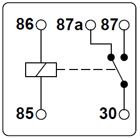
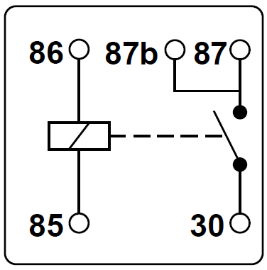
If there are any errors carefully check your. All examples shown are for spdt single pole double throw relays which includes any of the 5 10 or 20 amp relays on this site.
Automotive Relay Guide 12 Volt Planet
Normally open relay diagram. Connect the relay with hc11 port pins this is used to control on switches. The following schematic shows the basic circuit. Connecting additional devices to the. The diode prevents relay from arcing by giving a return path for the energy stored in the magnetic field of coil. Analyze the circuit determining all logic states for given input conditions. Check the accuracy of the circuits construction following each wire to each connection point and verifying these elements one by one on the diagram.
Relays control one electrical circuit by opening and closing contacts in another circuit. Basic schematic circuit diagram of relay. Carefully build this circuit on a breadboard or other convenient medium. Draw the schematic diagram for the relay circuit to be analyzed. Normally open single pole single throw spst relay. Single pole double throw spdt has three contacts.
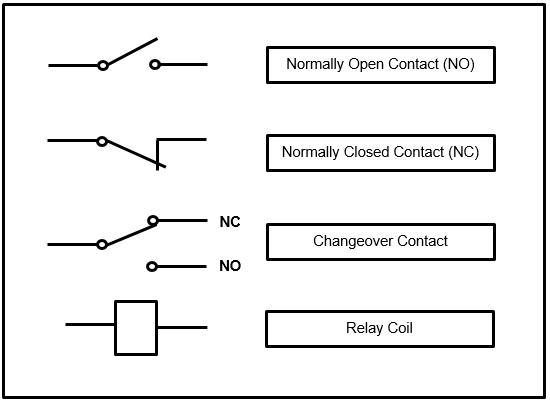
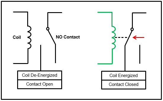
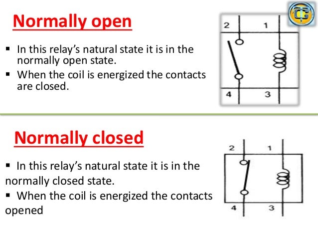
Relay diagrams quick reference last updated. In figure 2 we apply a dc voltage lets say 12v to the coil points. As relay diagrams show when a relay contact is normally open no there is an open contact when the relay is not energized. T most common are shown to the right. Diagrams will show how multiple relays one relay or another or just one relay can control your device. The transistor allows the hc11 to control the medium sized coil current of relay.
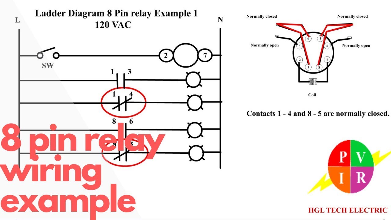
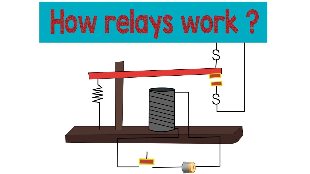
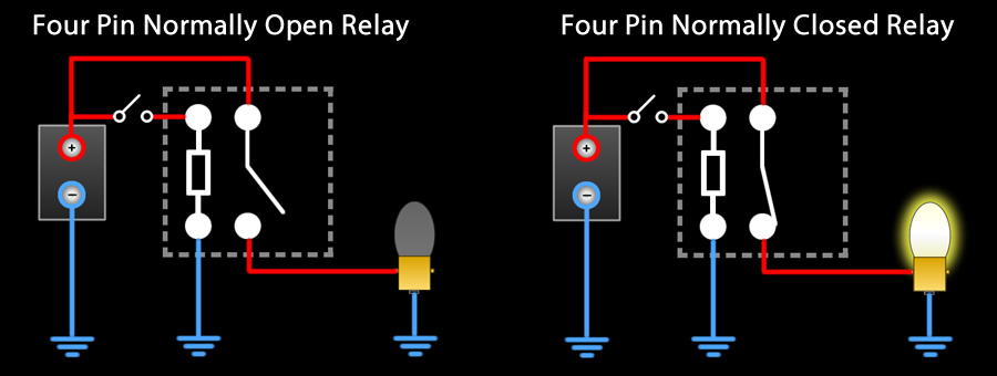
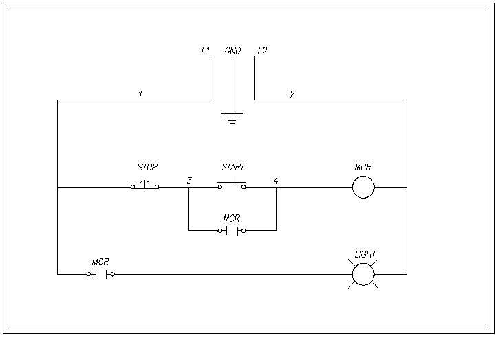
For instance the following diagram shows a normally open pushbutton switch controlling a lamp on a 120 volt ac circuit the hot and neutral poles of the ac power source labeled l1 and l2 respectively. When power is introduced an electromagnet pulls the first circuit into contact with the second thereby closing the circuit and allowing power to flow through. The no normally open connection of the relay is not connected until the relay turns on. Relay logic the com common connection of a relay is the part of the relay that moves. Single pole singl throw spst is the simplest with only two contacts. Video presentation of how the normally open spst relay works.
Some example is show in below. Visa versa normally open pole com is attached with coil when the coil of relay is magnetized. The lamp will energize only if someone presses the switch holding its normally open contacts in the closed position. Relays and switches come in different configurations. We can tell this switch is a normally open no switch because it is drawn in an open position. When the electricity turns off the circuit opens up again to stop the flow.
Carefully measure those logic states to verify the accuracy of your analysis. In figure 1 no dc voltage is applied to points a and b therefore no current flows through the coil of the relay the contact stays in the opened position and the fan will not be switched on because its disconnected from the 220v. Normally open switch contacts are sometimes referred to in. Normally open relays default in the open position meaning that when theyre not in use there is no contact between the circuits. When a relay is off the common is connected to the nc normally closed. This normally open starter kill relay application below relies on a ground from the alarm when disarmed and 12 volts from the ignition to enable the driver to start the vehicle.
Most alarms with this feature will not provide this grounded output when power 12 volts to the alarm is not present even if the alarm is grounded. Relays are switches that open and close circuits electromechanically or electronically. When a relay contact is normally closed. Check out the picture below to better understand how this process takes place. The normally closed. Starter kill normally open relay wiring diagram.
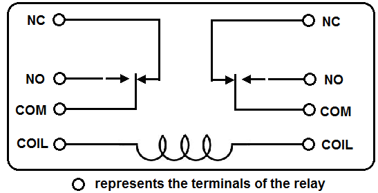
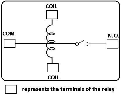
The contacts are usually labeled common com normally open no and normally closed nc.
Gallery of Normally Open Relay Diagram