If there are any errors carefully check your. Its a base model with 4 speakers.
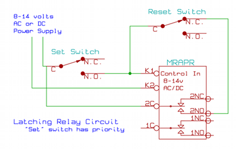
Latching Relay Circuit Schematic
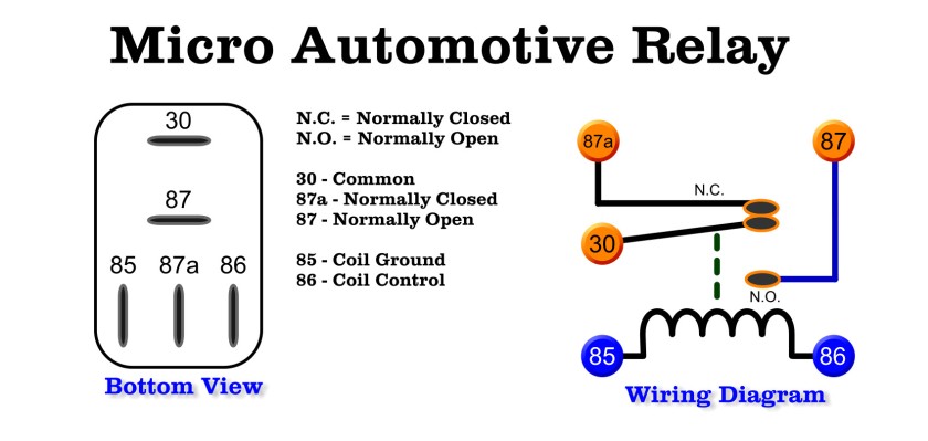
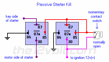
Normally closed relay wiring diagram. Starter kill normally closed relay wiring diagram the basic starter kill relay diagram shown below breaks continuity of the wire from the ignition switch to the starter motor or in some cases ie. If you want a normally closed relay you will want to wire to 87a. Wiring diagrams simple to complex ways to wire relays. Enginer control wiring diagram engine control relay passat wiring diagram engine control relay passat wiring diagram is available in our book collection an online access to it is set as public so you can download it instantly our book servers hosts in multiple locations allowing you to get the most less latency time to download any of our books like this one sxe10 altezza 3s ge engine control sxe10 3s ge engine control electrical parts location sxe10 3s ge summary engine control elec. 2 common 2 normally closed 2 normally open. This pinout image is only a 2 pole diagram for room on the page purposes but you can get the picture here with this one since a 3 pole will just have 1 more set of contacts.
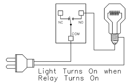
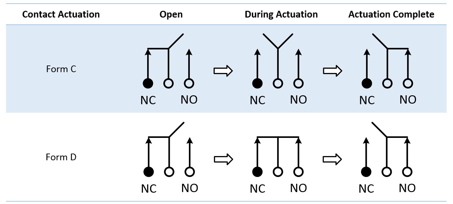
3 normally closed 3 normally open. Analyze the circuit determining all logic states for given input conditions. Ive been trying to find the stereo diagram for my 2013 verano. Output for a relay. Endgroup elbehery nov 10 16 at 1951 begingroup relays are always shown with the power off so nocomnc left to right as fakem at elbehery say. A 2 pole relay will contain 2 separate contacts.
Draw the schematic diagram for the relay circuit to be analyzed. This page demonstrates several simple ways to wire a relay for various applications. If you want a normally open relay you will wire to 87. 2013 buick verano base model stereo wiring diagram hello and thanks in advance for any help. Carefully build this circuit on a breadboard or other convenient medium. Relay logic the com common connection of a relay is the part of the relay that moves.
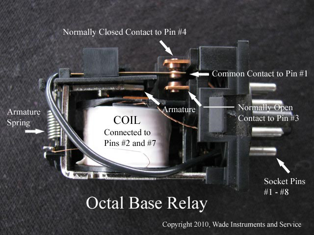
Begingroup the middle pin is always connected to the pin on the right normally closed whenever the relay is turned on this middle pin is connected to the pin on the left normally opened. Diagrams will show how multiple relays one relay or another or just one relay can control your device. Ford to another relay when the alarm is armed and the ignition is turned on. You should definitely test this using a multi meter. As you can see there is absolutely no difference between the square type and the round type other than. All examples shown are for spdt single pole double throw relays which includes any of the 5 10 or 20 amp relays on this site.
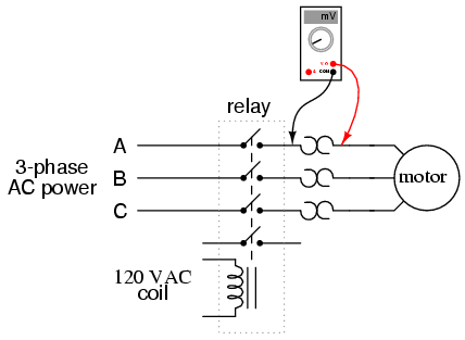
For instance the following diagram shows a normally open pushbutton switch controlling a lamp on a 120 volt ac circuit the hot and neutral poles of the ac power source labeled l1 and l2 respectively. The square relay pinout shows how the relay socket is configured for wiring. Carefully measure those logic states to verify the accuracy of your analysis. Havent had any luck online and would greatly appreciate and help in the rig. Check the accuracy of the circuits construction following each wire to each connection point and verifying these elements one by one on the diagram. Although most relays are labeled at the bottom you can always find the 30 pin set perpendicular to pins 87 and 87a for easy identification to the power source.
I cant tell which is. I remember buying a relay module from a chinese vendor and this drawing was wrong.


