Clear easy to read diagrams and instructions for wiring a switched outlet where a wall switch can control the receptacle. It shows how the electrical wires are interconnected and can also show where fixtures and components may be connected to the system.

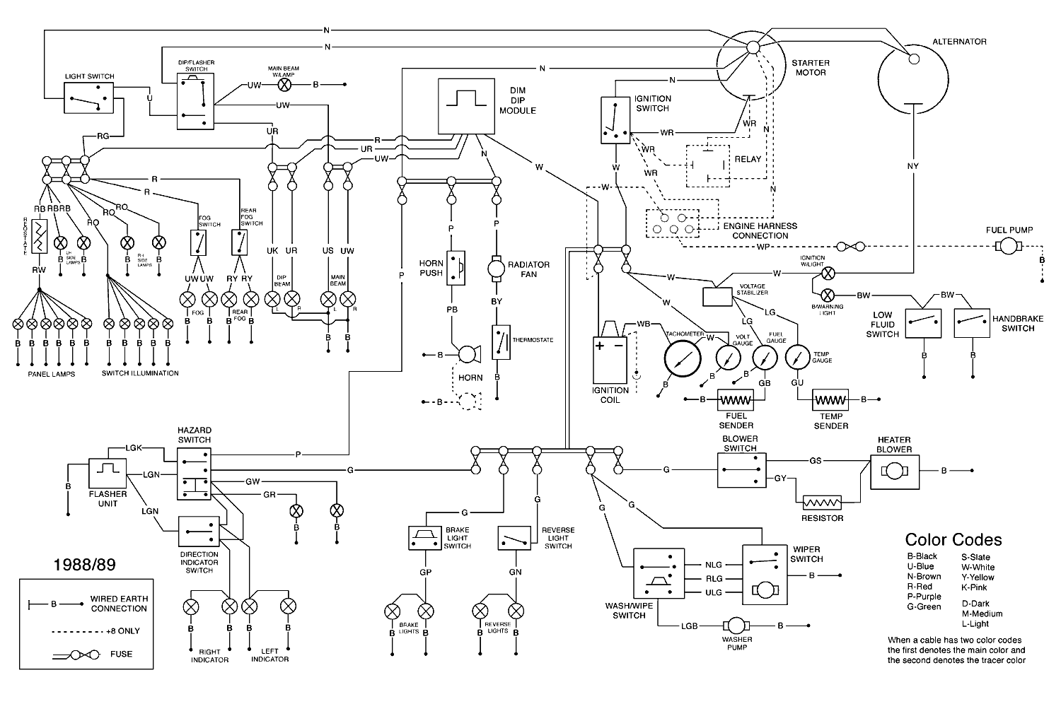
1991 Mr2 Bgb Online Electrical Electrical Wiring Diagrams
How to read electrical wiring diagrams. For all the electronics hobbyist wannabes this is a must read instructable. Being able to master this competency will not only help you find solutions to common electrical problems a lot faster but will also give you a big headstart compared to less qualified technicians. And its not that hard at all. Learning to read car wiring diagrams is an awesome skill to add to your auto mechanic skillset. The electrical wiring diagram consists of two types such as a single line wiring diagram and a multi line wiring diagram. Learn to read electrical and electronic circuit diagrams or schematics.
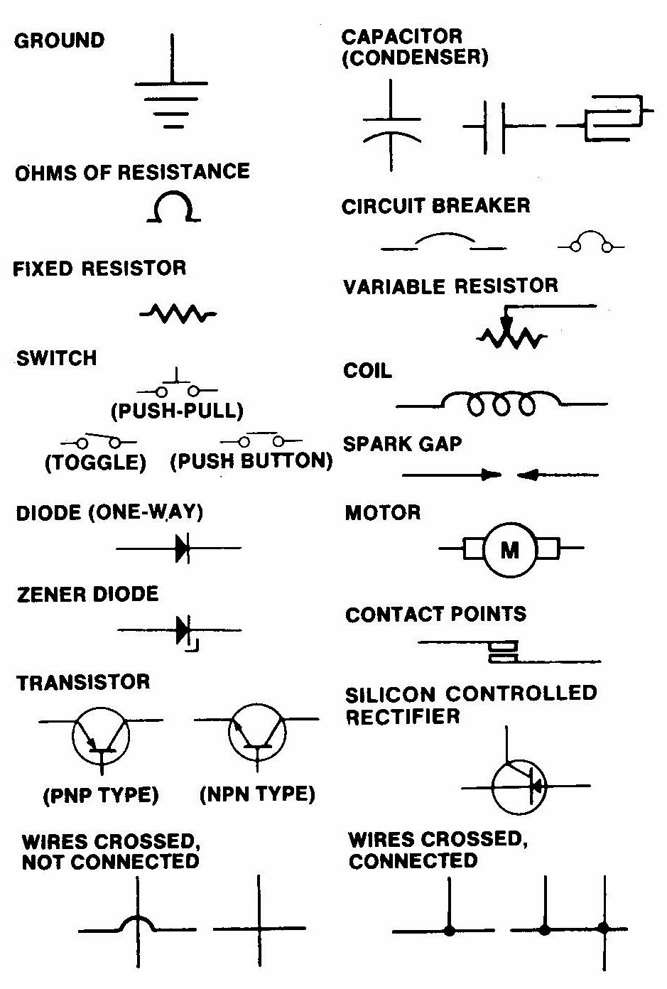
A list of electrical symbols and descriptions can be found on the electrical symbol page. Home page trim molding electrical wiring building remodeling wall repair house painting cleaning repair diy videos. Working with wire or skip the breadboard and jump straight into wiring stuff up. This instructable will show you exactly how to read all those confusing circuit diagrams and then how to assemble the circuits on a breadboard. A drawing of an electrical or electronic circuit is known as a circuit diagram but can also be called a schematic diagram or just schematic. Wires are used to connect the components.
A diagram that represents the elements of a system using abstract graphic drawings or realistic pictures. Check local regulations for. Calculate total conductors allowed in a box before adding new wiring etc. Knowing how to cut strip and connect wire is an important electronics skill. Knowing how to read circuits is a very useful skill that will help you out all the time. Breadboards are a great way to make temporary functional prototype circuits.
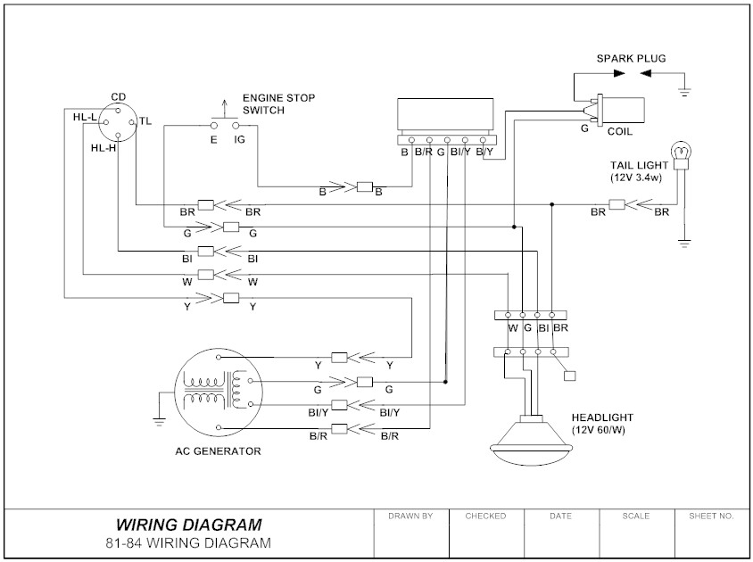
For example in our diagram 2111e means that contact goes to 21 st page and the junction of 11. The box is marked with the numbers and alphabets followed by the page number. In addition to reading this instructable it may be a good idea for you to read my other instructable. Especially if you start messing around with building little electronics projects. A wiring diagram is a simple visual representation of the physical connections and physical layout of an electrical system or circuit. Circuit or schematic diagrams consist of symbols representing physical components and lines representing wires or electrical.
To read a wiring diagram first you have to know what fundamental elements are included in a wiring diagram and which pictorial symbols are used to represent them. A line represents a wire. See their number is in the horizontal axis and alphabets in the vertical axis. By code the number of conductors allowed in a box are limited depending on box size and wire gauge. Read electrical wiring diagram. How to use a breadboard now that you know how to read schematics why not make one.
Refer to the figure an electrical wiring diagram is surrounded by the rectangular box. Switched outlet wiring diagrams. A diagram that uses lines to represent the wires and symbols to represent components. To understand how to read ladder wiring diagrams lets start with a simple electrical schematic consisting of a power supply switch and light then you will move on to our control panel sample wiring diagrams. Electrician circuit drawings and wiring diagrams youth explore trades skills 3 pictorial diagram. On electrical diagrams fuses are often located on a different page than the circuit they protect.
Once you get the hang of the most basic notions. To begin understanding how to read and understand electrical circuit diagrams take our basic circuit and draw it out as it would. The common elements in a wiring diagram are ground power supply wire and connection output devices switches resistors logic gate lights etc.


