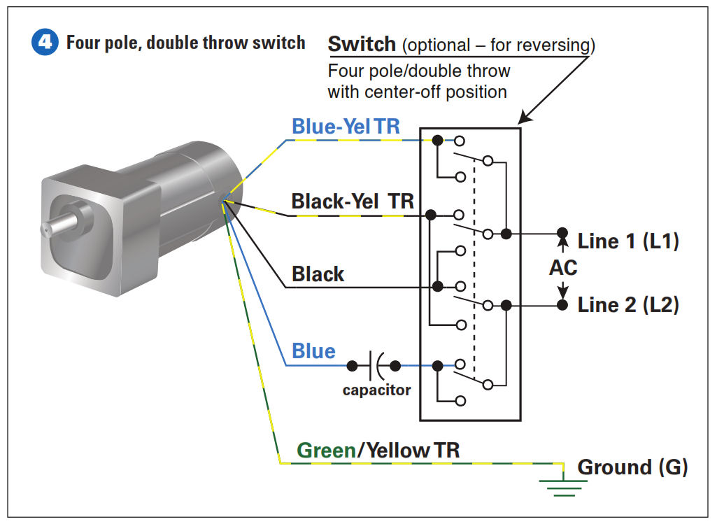
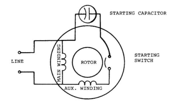
Dual run capacitor diagram wiring diagrams click motor run capacitor wiring diagram wiring diagram consists of numerous in depth illustrations that present the relationship of various things. The auxiliary starting winding is displaced in space from the main winding by 90 degrees.
Single Phase Induction Motors Electric Motor
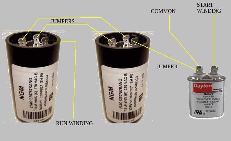
Electric motor capacitor wiring diagram. This type of winding. Assortment of dayton capacitor start motor wiring diagram. A wiring diagram is a streamlined conventional photographic representation of an electrical circuit. It reveals the parts of the circuit as streamlined forms and also the power and also signal connections between the tools. A wiring diagram is a simplified traditional photographic depiction of an electrical circuit. A wiring diagram is a streamlined traditional photographic depiction of an electric circuit.
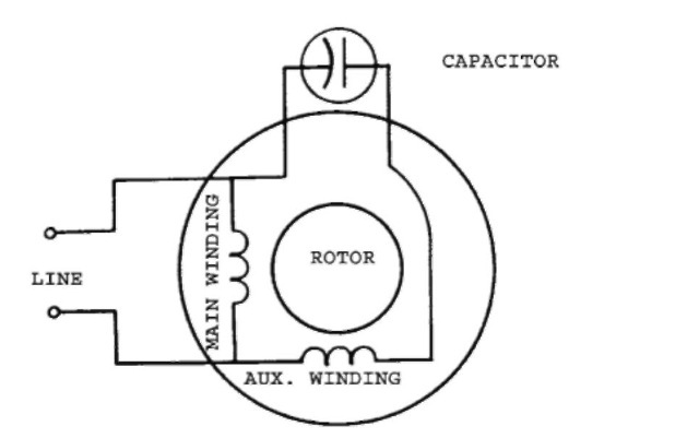
A circuit is usually composed by many components. There are two things which are going to be present in any single phase motor wiring diagram with capacitor. It also has a centrifugal switch and starting capacitor. It shows the components of the circuit as simplified shapes as well as the power and signal connections in between the devices. The other thing that you will get a circuit diagram would be traces. Split phase single value capacitor electric motor dual voltage type.
It includes directions and diagrams for various varieties of wiring techniques and other products like lights home windows etc. Also read about the speed torque characteristics of these motors along with its different types. Wondering how a capacitor can be used to start a single phase motor. Types of single phase induction motors electrical a2z single phase induction motors are traditionally used in residential applications such as ceiling fans air conditioners washing machines and refrigerators single phase motor wiring with contactor diagram the plete guide of single phase motor wiring with circuit breaker and contactor diagram. Variety of marathon electric motor wiring diagram. Click here to view a capacitor start motor circuit diagram for starting a single phase motor.
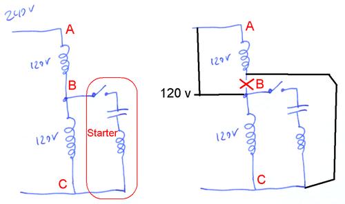
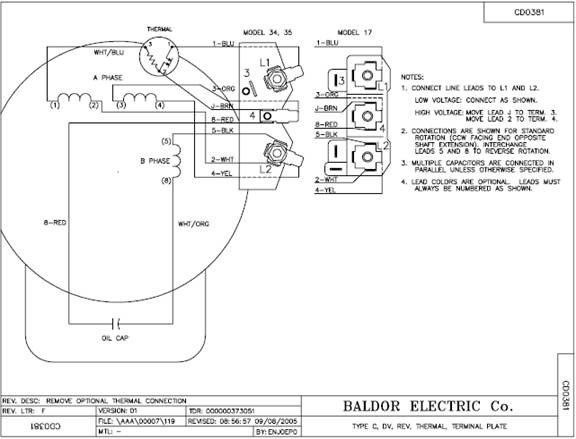
It reveals the parts of the circuit as streamlined shapes and the power and also signal connections between the tools. When the main windings are connected in series 120 volts is used. This motor has two identical main windings arranged for either series or parallel connections. With the main windings connected in parallel the line voltage is usually 240. The first component is symbol that indicate electrical element in the circuit. Collection of electric motor capacitor wiring diagram.
Single phase motor wiring diagram with capacitor start. Variety of baldor motor capacitor wiring diagram. A wiring diagram is a streamlined standard photographic representation of an electric circuit. It shows the elements of the circuit as simplified shapes and the power and signal links between the tools. Learn how a capacitor start induction run motor is capable of producing twice as much torque of a split phase motor.
Gallery of Electric Motor Capacitor Wiring Diagram