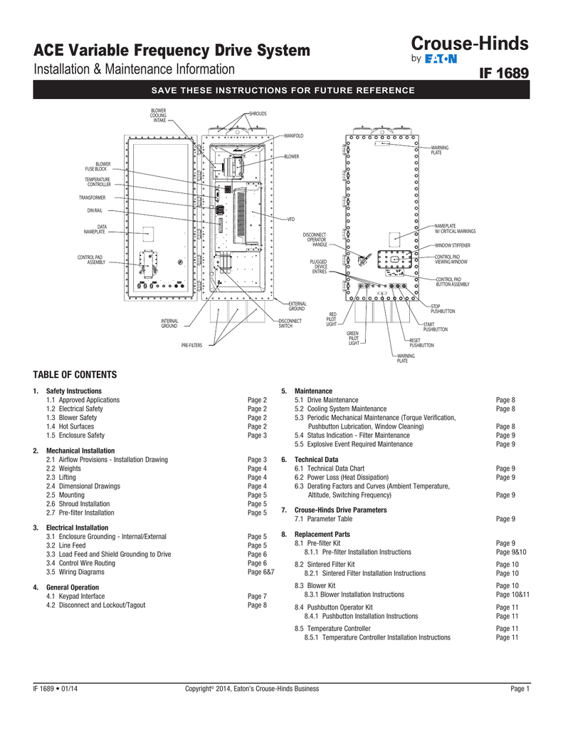
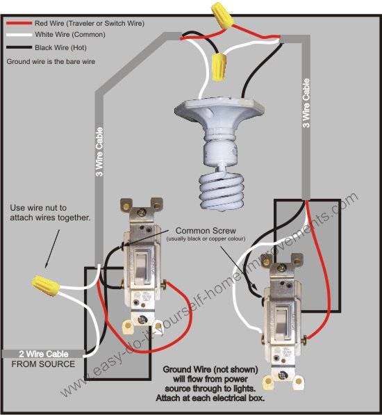
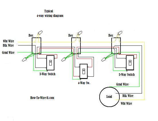
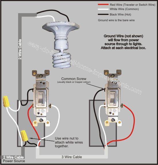
They show the relative location of the components. Starter for compressor motor at cutler hammer wiring diagram eaton wiring.

Contactor Wiring Diagram With Timer Diagram Diagramtemplate
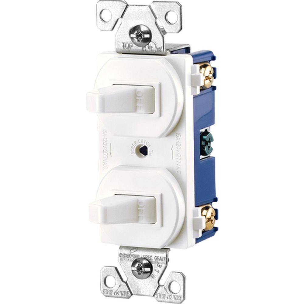
Eaton light switch wiring diagram. Fully explained wiring instructions complete with a picture series of an installation and wiring diagrams can be found here in the gfi and light switch area here in this website. Eatons full line of decorator and standard toggle switches are perfect for residential and commercial applications. Do you offer a combination switch and receptacle that has a small indicator light on the switch. They can be used as a guide when wiring the controller. The source is at sw1 and 2 wire cable runs from there to the fixtures. Can i use 7501w or 1107w.
What is a rocker switch. The black hot wire connects to the far right switchs common terminal. The sensor black wire will connect to the hot wire black in the wall box. Do you have a decorator switch for aluminum wiring. In this diagram power enters the fixture box. Red and blue wires link traveler terminals of both switches.
Figure 1 is a typical wiring diagram for a three phase mag. Just click the wiring diagrams. This 3 way light switch wiring diagram shows how to do the light switch wiring and the light when the power is coming to the light fixture. Industrial 56 receptacles 65. The sensor red wire will connect to the wire which goes to the light fixture. What is the difference between 7501 and 7501 9.
What does coalr stand for. 4 days ago k1ccn westinghouse eaton cutler hammer lifeline series oem furnas eaton dpngb wiring diagram 29 wiring diagram images wiring. The hot and neutral terminals on each fixture are spliced with a pigtail to the circuit wires which then continue on to the next light. Do you offer auto ground feature on your switches. Multiple light wiring diagram. Where can i find installation instructions for the anyplace switch.
Eatons wiring devices technical support. For single pole applications wire the sensor switch according to wiring diagram 1 using the wire nuts provided. Our heavy duty and hazardous area switches provide safety reliability and long term durability in industrial environments. This diagram illustrates wiring for one switch to control 2 or more lights. What is the difference between a toggle and decora switch. Wiring diagrams sometimes called main or construc tion diagrams show the actual connection points for the wires to the components and terminals of the controller.
The sensor blue wire is not used and should be capped off with a wire. What is the difference between a single pole and a 3 way switch.


