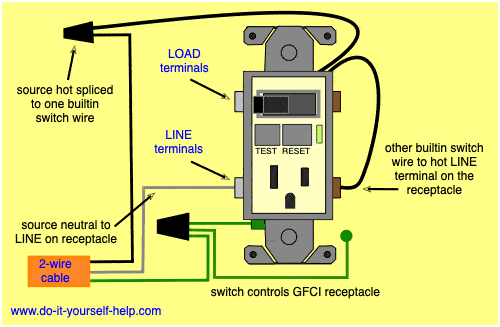
Always review the safety page on our website. Wiring a gfci outlet with a light switch.

Double Receptacle Wiring Three Wire H1 Wiring Diagram
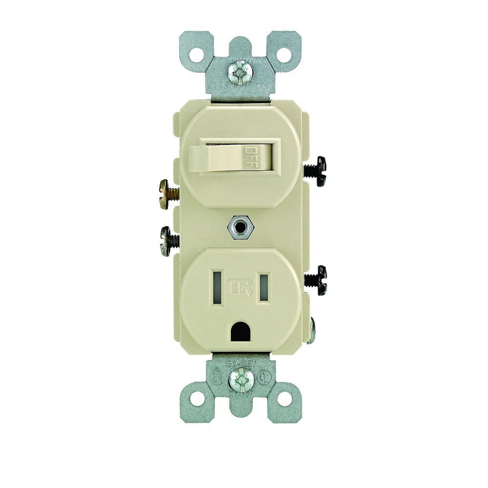
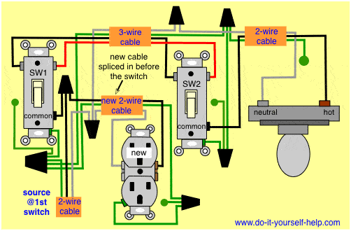
Duplex toggle switch wiring diagram. This tab is removed to isolate the tabs from each other. The usual practice in home construction is to use 3 way switches. Half switched outlet wiring diagrams. How 3 way and 4 way switch circuits work controlling a light with two or more switches this page describes how to use 3 way and 4 way switches to control lights from two or more locations. The switchreceptacle combo device is set up like a duplex receptacle but has a 15a single pole switch in one half and. They come in single pole and 3 way.
As with any electrical project make sure that you take all necessary precautions most important being to make sure you shut off the power. In addition to slots for stripping insulation from 14 and 12 gauge wire it has slots to strip the. This wiring diagram illustrates adding wiring for a light switch to control an existing wall outlet. Here are four must have tools if you plan to wire many switches and outlets. The two conductor wiring diagram at the top of this page is from older homes and is likely not used much anymore depending on which code book is in force in each jurisdiction. The hot source wire is removed from the receptacle and spliced to the red wire running to the switch.
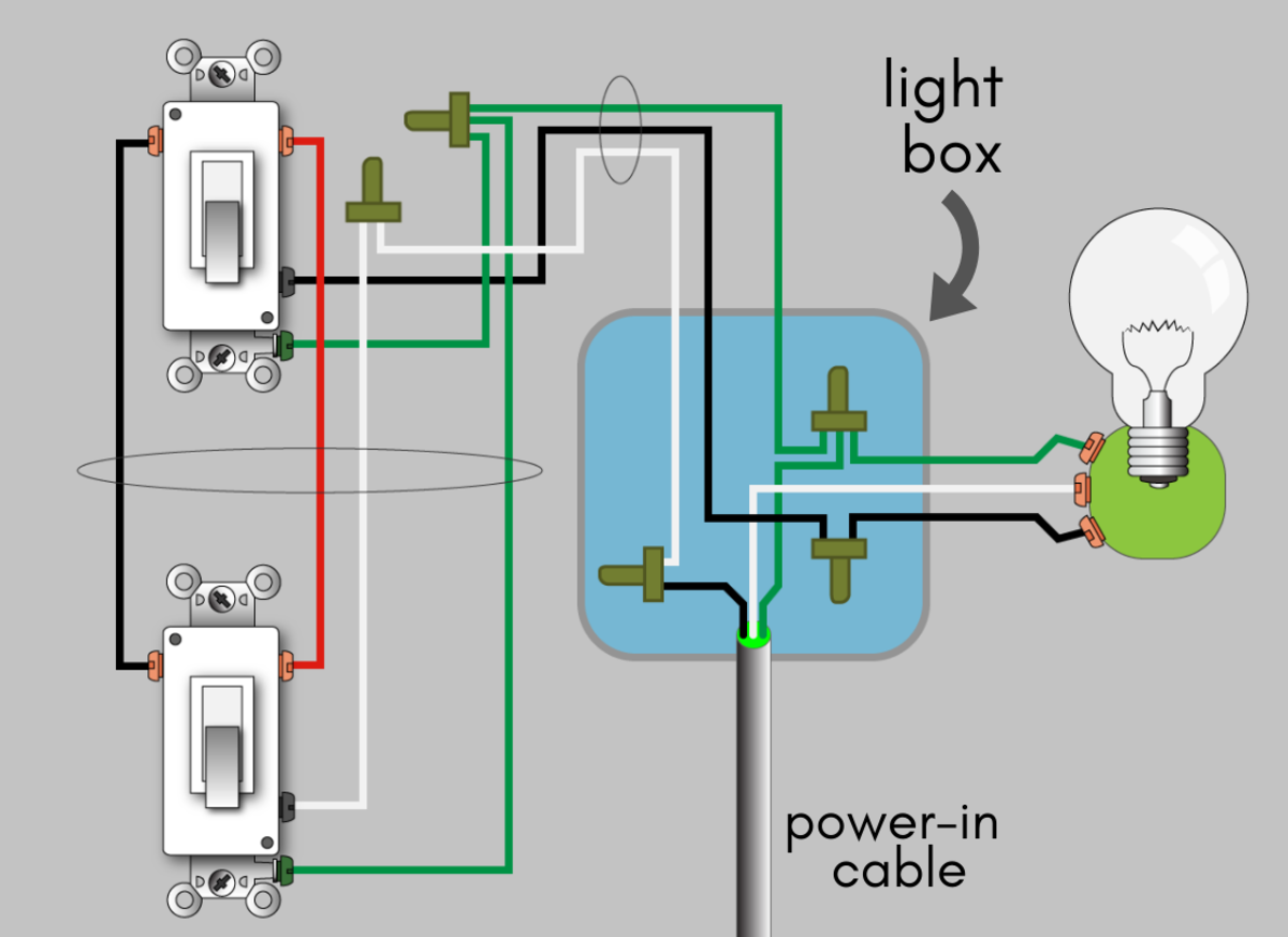
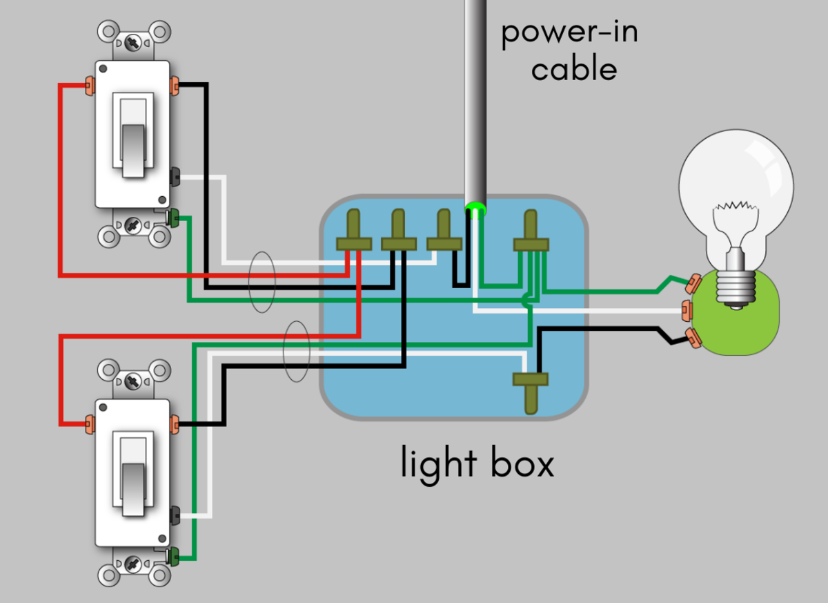
A light or lights can be controlled by more than one switch. Combination sheath and wire stripper. This page contains wiring diagrams for two outlets in one box. Another valuable resource available on our site is the basics of household wiring dvd which is also available as an instantly downloaded e book. Follow this link to get your copy. The source is at the outlet and a switch loop is added to a new switch.
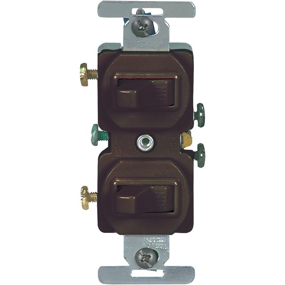
The following two switched outlet wiring diagrams depict how split or half switched outlets can be wired. Just touch the probes between a hot and a neutral or between two hot wires. A duplex switch contains two switches on one body. Wiring two outlets in one box. The two conductor cable from the ceiling box to the light switch is supposed to have the white conductor re identified with another color because it is not being used as a neutral but as a hot wire. Sparky channel 30709 views.
Click here for an overview of all these pages. You can pick one up for a few bucks and use it to test for hot wires or to find a neutral. All of article 404 pertains to the installation of switches. The tester will light up if the wires are hot the tester shown also tests for 240 volts. A two conductor cable is run from the the switch box to another duplex receptacle outlet that is also live at all times. The black wire from the switch connects to the hot on the receptacle.
Separate switches for bath fan and light from single switch in a 1960s house duration. The first one shows the method with the neutral conductor in the switch box. In the first diagram the single way switch and light bulb is connected to the load terminal of gfci. Two of the common terminals are connected together with a removable metal tab. Included are arrangements for 2 receptacles in one box a switch and receptacle outlet in the same box and 2 switches in the same box. 3 way switch wiring diagram.
This way the switch and light bulb is gfci protected. These terminals are usually connected to line voltage and can be black or bronze color depending on the manufacturer. With each outlet connected by its own pigtail wire if one fails because of physical damage. This is the first of several related pages explaining how to control lights with multiple switches. In this diagram two duplex receptacle outlets are installed in the same box and wired separately to the source using pigtails spliced to connect the terminals of each one. Although that is the code requirement it has not been put.
How to wire gfci combo switch and outlet gfci switchoutlet wiring diagrams.
