Round dual capacitors on the top should be marked. A wiring diagram is a type of schematic which makes use of abstract pictorial symbols to show all the affiliations of parts in a system.

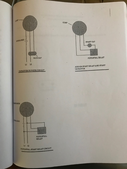
Solved Start Cap Runcap Potential Rblay Adoon Start Relat
Dual capacitor wiring diagram. Condensing unit dayton model. Ac dual capacitor wiring diagram download emerson electric motor wiring diagram fresh single phase with wiring diagram for electric motor with capacitor best single phase exactly whats wiring diagram. Installs with all. Wiring diagrams dmshvacpartners. Another method is the capacitor start induction run motors. Ac dual run capacitor wiring diagram.
Rule of thumb on wiring the capacitor is. In this video zack psioda explains how many dual run capacitors are wired in heat pump and. Hobbyist diy electronic devices amp. Many people have asked about my dual capacitor wiring scheme for my stratocasters so i thought id put together a short how to video regarding this simple modification. Hvac shop talk podcast represents the blue collar boys and girls in the skilled trades especially hvac. 3 terminals capacitor air conditioner wiring diagram hindi air conditioner repair service in mira road review link httpsgoogleqotgd call.
Dual run capacitor diagram wiring diagrams click motor run capacitor wiring diagram wiring diagram consists of numerous in depth illustrations that present the relationship of various things. We know about the activity of a. It includes directions and diagrams for various varieties of wiring techniques and other products like lights home windows etc. Circuitry representations are made up of two points. Hvac shop talk podcast represents the blue collar boys and girls in the skilled trades especially hvac. Dual capacitor single phase field supply l1 l2 grd grounding screw c s r c y comfort alert t1 t2 l1 l2 hps lps used in r410a models only contactor r start capacitor start relay 5 2 black w with k hash comp orange low voltage terminals see note 6 red red defrost thermostat t2 dft test t1 t2 c y o w2 r dft e c y o w2 r e df1 df2 black black reversing valve solenoid yellow cc w black blue black defrost control board yellow 1 cch yellow l l select models only black blue black r c s black.
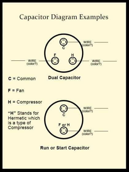
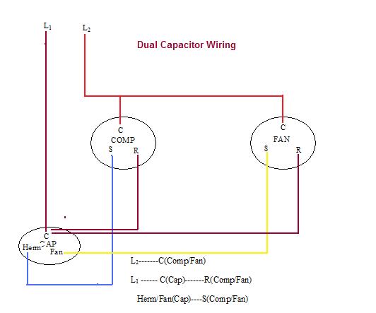
Herm com and fan. Herm connects to the hermetically sealed compressor. You would need to look at the wiring diagram that came with the unit. One often used method is the split phase motors. Usually the wiring diagram is glued to one of the panels on the air conditioner. Keep in mind the compressor also often needs a capacitor which will be herm compressor.
Buying a new hvac capacitor a new capacitor should always be installed with a new. The single phase induction motor can be made to be self starting in numerous ways. Load devices and explain how they are represented on circuit diagrams. Changed capacitor and fan motor as the old motor was seized up. Fan connects to the condenser fan motor. Icons that represent the components in the circuit as well as lines that represent the connections in.
Herm on capacitor goes to the start winding on the compressor fan on capacitor goes to brown fan wire that goes to the fan and com on the capacitor comes off one leg of the contactor to provide power to the. Com connects to the contactor and provides power to the capacitor. A dual capacitor has three connections herm fan and com. Diagram explanation of how a capacitor is used to start a single phase motor. Run capacitor and why not to use it in a power strip. In this video zack psioda explains how many dual run capacitors are wired in heat pump and.
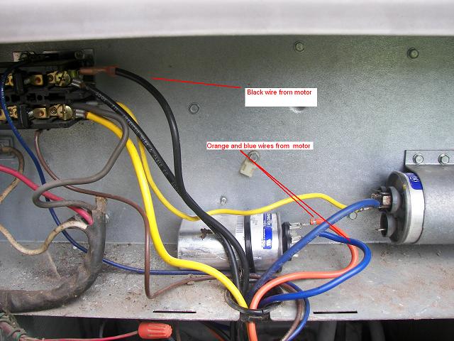
If the unit has two capacitors then one is the run capacitor and the other is the start capacitor. W0g6710778replacement fan motor us motors model k55hxclp 1470 208230 ph1 60hz 20a thermally protected 825 rpm 60 celcius ambientthe old motor had 4 wires l1 l2 brwnwht which is hooked up at the dual cap fan port. Hope you can read it.


