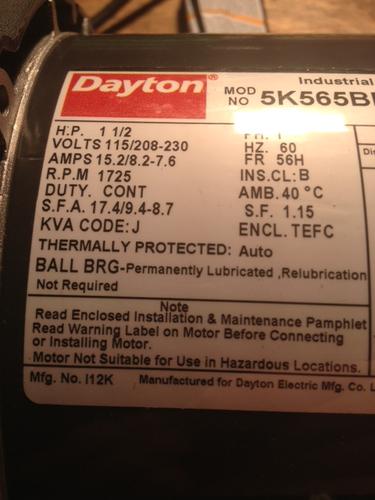
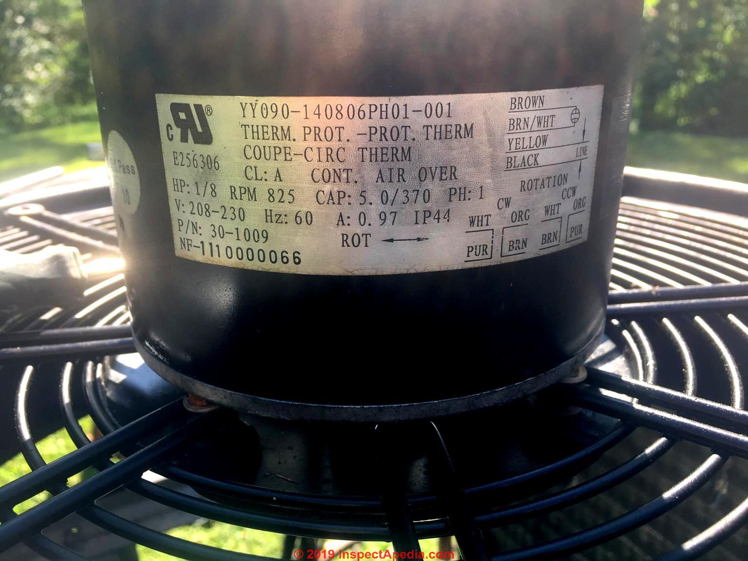
Dayton blower motor wiring diagram wiring diagram general pdf. 50 hz for use in machinery air compressors conveyors fans blowers machine tools speed reducers pumps and industrial equipment in noncombustible environments.

Wire Size For Motor
Dayton industrial motor wiring diagram. Collection of dayton electric motors wiring diagram. Dayton motor wiring diagram download read online. It shows the components of the circuit as simplified forms and the power and signal connections between the devices. 3 wire compressor diagram wiring diagram symbols and guide pdf. Wiring 110 motor with capacitor reading industrial wiring pdf. Dayton 110 220 volt motor wiring.
Harley wiring diagram wires wiring diagrams pdf. Dayton manufactures an extensive range of alternating and direct current electric motors. Easy online ordering for the ones who get it done along with 247 customer service free technical support more. Download dayton motor wiring diagram free files. A wiring diagram is a simplified conventional pictorial representation of an electric circuit. Dayton farm duty motor wiring diagram wiring diagram is a simplified adequate pictorial representation of an electrical circuit.
Line 1 straight 120 volts to t1 drum switch. Mechanical features provide long life in high tension belt type loads which. Wire your drum switch as below. It shows the components of the circuit as simplified shapes and the capability and signal associates surrounded by the devices. Terminal 1 line 2 120volt power terminal 2 t4 terminal 3 t5 terminal 4 t8 terminal 5 t2 and t3 terminal 6 no connection you need a safety switch in line of the 240 volt to turn all power off for maintenance or any work on the machinethe drum switch will stop the motor in the off position but all power is not removed. Download dayton motor wiring diagram pdf.
Dc to ac motor wiring diagram schematic wiring diagram pdf. Looking for dayton 34 hp belt drive motor capacitor start 1725 nameplate rpm 115 230110 220 voltage frame 56 6k376. This video explains how the wiring connections are made based on the wiring diagram provided with the motor. Although wiring the peripheral accessories such as speed controllers fuses and switches for a dayton electric motor can be a reasonably complex task most electric motors including those made by dayton use two wired connections linked directly to a speed controller or switching device. Graingers got your back. 3ø wiring diagrams 1ø wiring diagrams diagram er9 m 3 1 5 9 3 7 11 low speed high speed u1 v1 w1 w2 u2 v2 tk tk thermal overloads two speed stardelta motor switch m 3 0 10v 20v 415v ac 4 20ma outp uts diagram ic2 m 1 240v ac 0 10v outp ut diagram ic3 m 1 0 10v 4 20ma 240v ac outp uts these diagrams are current at the time of publication.
The one you have will work fine they are used often at motor. Air compressor motor direct replacements for selected air compressors. From industrial applications like driving a punch press to agriculture uses such as managing a hatchery for chickens count on dayton motors for the design features you need.


