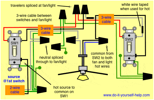
Ceiling fan wiring diagram. Ceiling fan switch wiring diagram 2 line voltage enters the switch outlet box and the line wire connects to each switch.
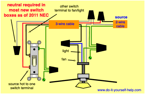
Wiring Diagrams For A Ceiling Fan And Light Kit Do It
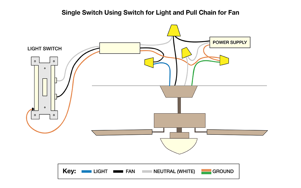
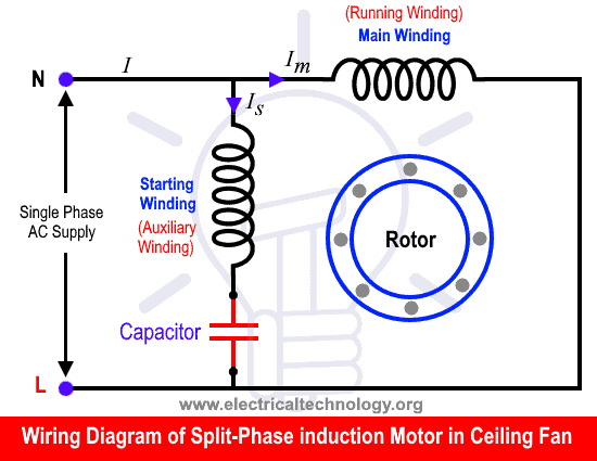
Ceiling fan wiring diagram. According to previous the traces in a ceiling fan internal wiring diagram represents wires. This diagram is similar to the previous one but with the electrical. Injunction of 2 wires is generally indicated by black dot to the intersection of 2 lines. Wiring diagram 1 power enters at the wall switch box power starting at the switch box this wiring diagram shows the power starting at the switch box where a splice is made with the hot line which passes the power to both switches and up to the ceiling fan and light. However it doesnt imply link between the cables. To wire a 3 way switch circuit that controls both the fan and the light use this.
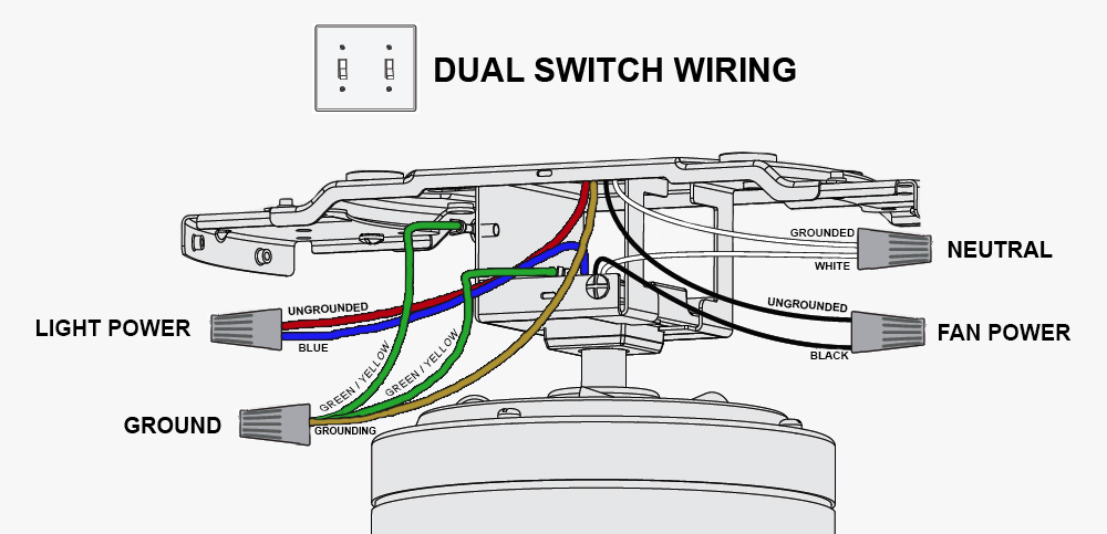
Installing a ceiling fan. This might seem intimidating but it does not have to be. Wiring diagrams for ceiling fan and light kit wiring diagram fan and light with source at ceiling. With these diagrams below it will take the guess work out. Switched lines and neutral connect to a 3 wire cable that travels to the lightfan outlet box in the ceiling. Occasionally the wires will cross.
Pick the diagram that is most like the scenario you are in and see if you can wire up your fan. A question we often get asked is where can i find a wiring schematic or wiring diagram for my ceiling fan. Take a closer look at a ceiling fan wiring diagram. The fan control switch usually connects to the black wire and the light kit switch to the red wire of the 3 way cable. Whether it be a hampton bay hunter or another brand of ceiling fan many fans have the same setup in terms of installation. 3 way fan switch wiring diagram.
With the below wiring diagrams you can install 90 of ceiling fans no matter the make or model.


