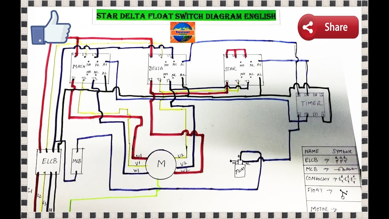
380v connect pump without air switch 2connect probe wires according to the following sketch if need. Single phase wiring diagrams single phase wiring diagram for 05hp pumps with governor switch single phase wiring diagram with governor switch single phase wiring diagram without governor switch three phase wiring diagrams three phase 208v wiring diagram three phase 230v wiring diagram three phase 460v wiring diagram three phase 575v wiring.
Goulds Booster Pumps Buyers Guide
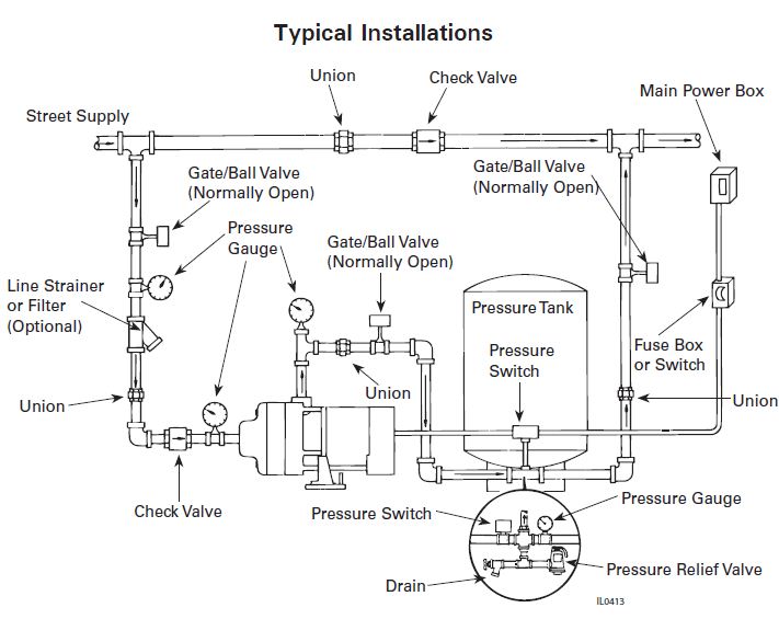
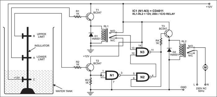
Booster pump control wiring diagram. Here is the complete guide step by step. Booster pump control panel booster pump system booster pump booster pump working booster pump working animation polaris booster pump bearing replacement smart buddie booster pump booster. A two wire single pole single throw float switchthe rising action of the float can either close ie turn on a normally open circuit or it can open turn off a normally closed circuitinstallation scenarios might include a normally open float switch turning on a pump to empty a tank control schematic 2 or a normally closed float switch turning off a pump that fills a tank control schematic 1. In this video we will look at the control wiring for a 3 phase pump panel and how a pump is controlled both in auto mode as well as hand mode. A wiring diagram is a simplified traditional photographic depiction of an electric circuit. Electrical guru is shoing in this video how the water tank is refilling automatically and its full system how its working full deffination for booster pump and submersible pump with panel.
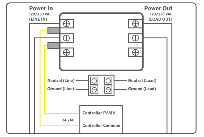
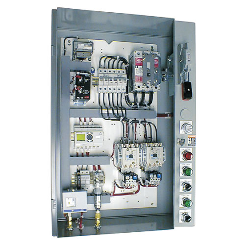
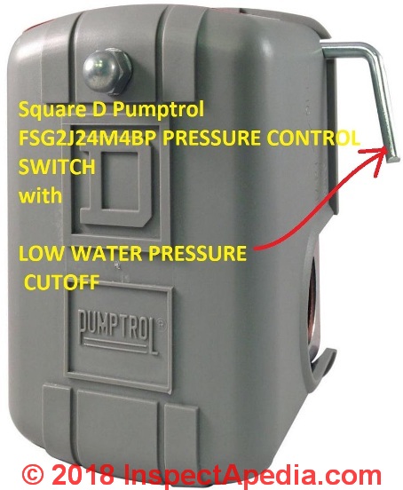
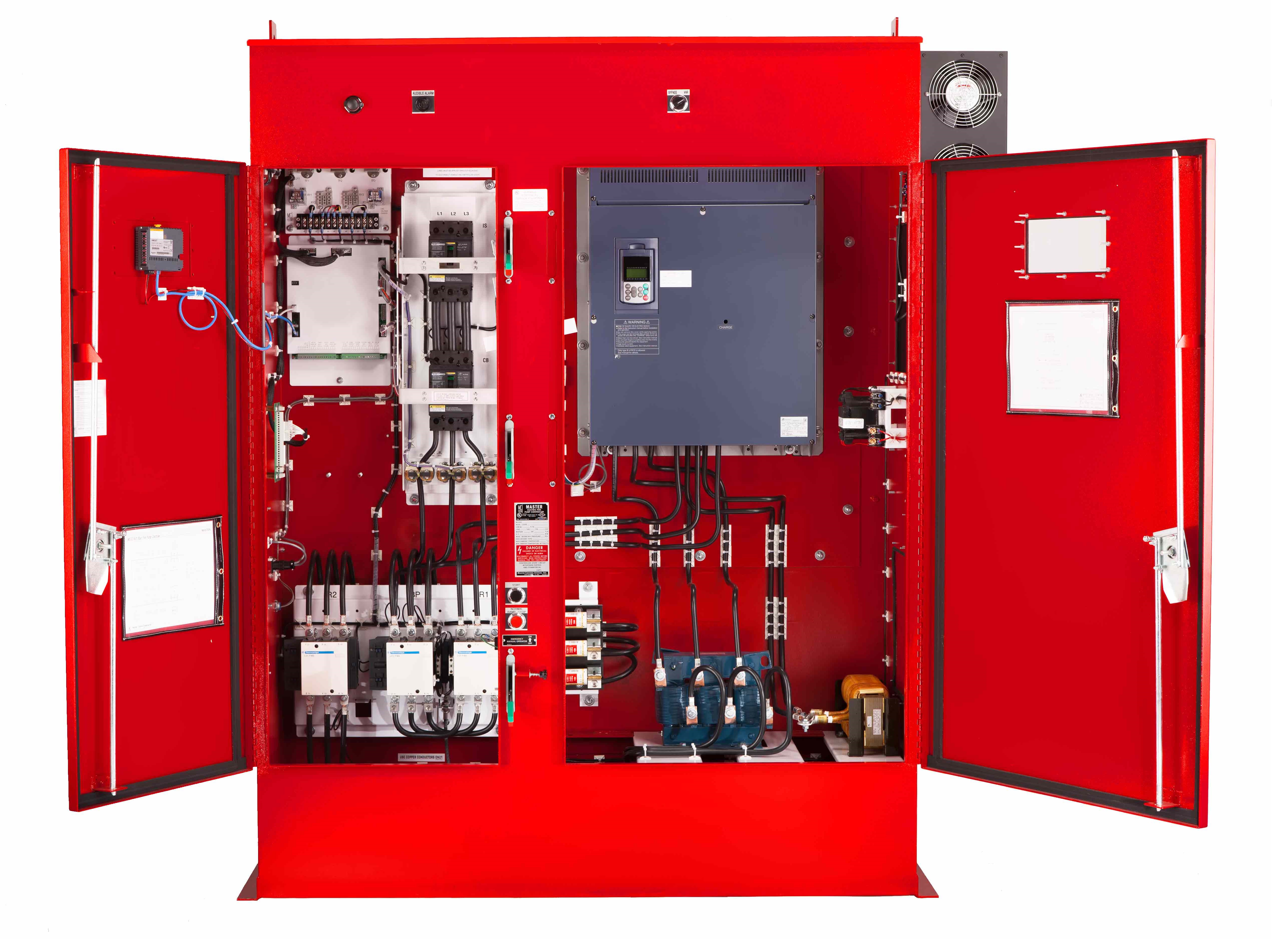
It shows the parts of the circuit as simplified shapes as well as the power as well as signal links between the devices. Assortment of pump control panel wiring diagram schematic. Fix the control on the wall open the junction box connect the power supply and pump wires according to the label. Iv installation guide and wiring diagram 4 note. Electrical cabinet home electrical wiring electrical installation electrical engineering solar panel battery solar panel kits solar panels landscaping near me. Electrical engineering books electrical projects electrical installation electronics projects engineering projects engineering technology electrical wiring colours ladder logic power lineman.
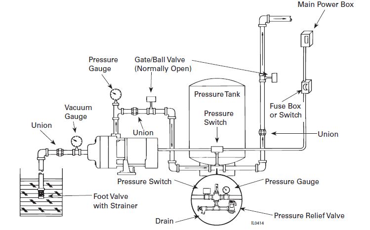
380v connect pump input vol. Single phase submersible pump control box wiring diagram 3 wire submersible pump wiring diagram in submersible pump control box we use a capacitor a resit able thermal overload and dpst switch double pole single throw. More ideas for you. The booster pump is a polaris pb4 34hp 3450rpm 230115v the booster pump is not connect at this stage the above diagram show the booster pump wired to the same location as the smartpure oxidizer the oxidizer will be eliminate. The wiring connection of submersible pump control box is very simple. In auto mode the pump will start using a standard.
Offoffoff with air switch null input vol. Strictly forbid to install the control box in the places as following. Lets start with the most basic float switch. Please note that probe wires should not be short circuit and against the tank wall. Remote control pump control panels for water booster pump system. Saved by edvard csanyi.
Gallery of Booster Pump Control Wiring Diagram