255 time to complete. Consult an abyc certified marine electrical professional for system.

Solar Boat Wiring Diagram H1 Wiring Diagram
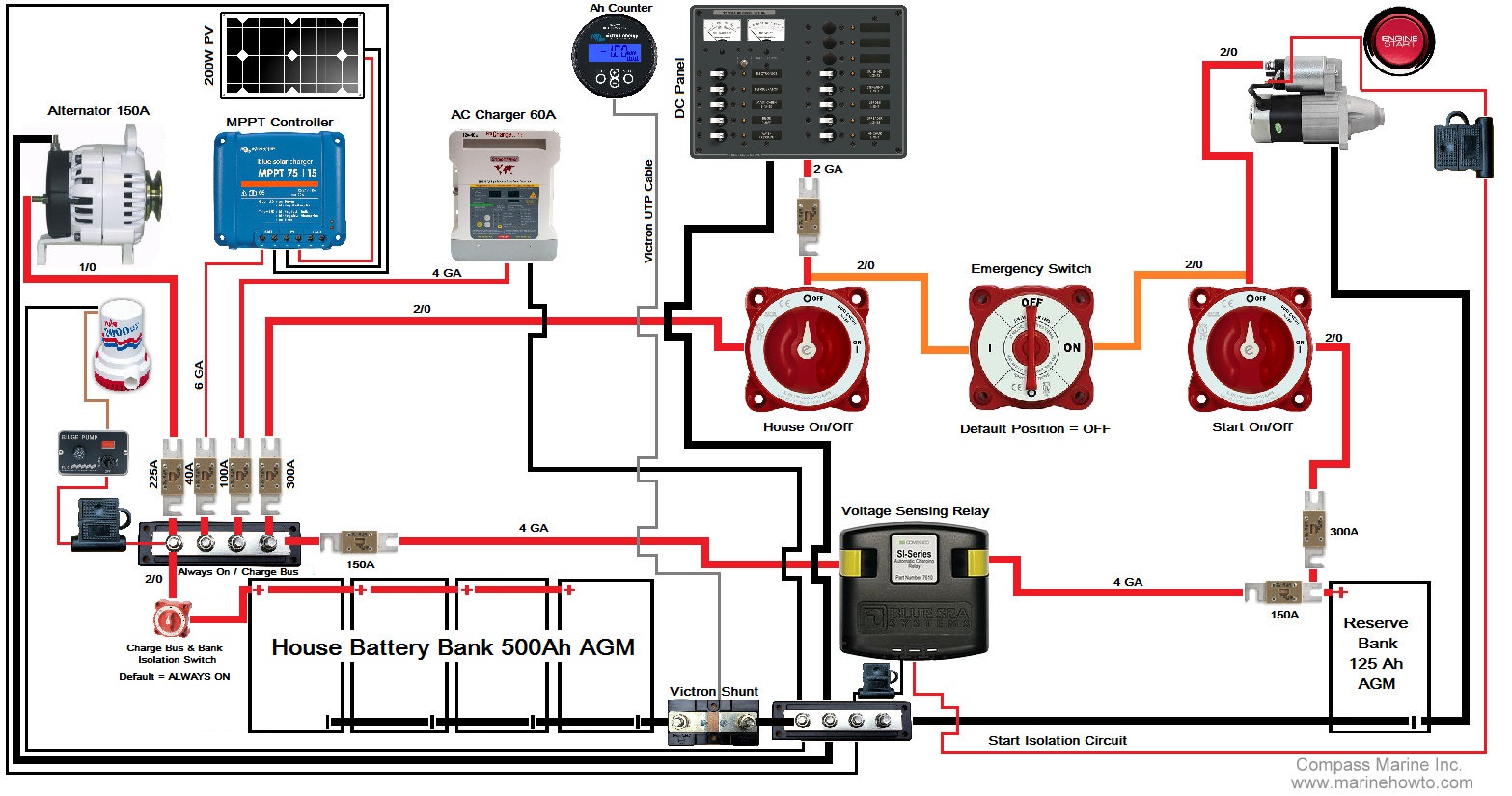
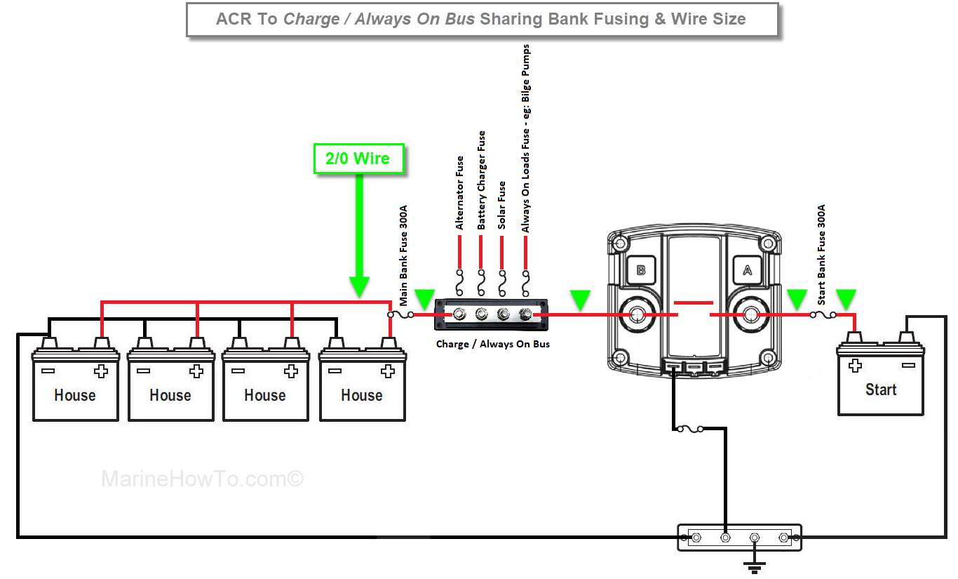
Boat battery charging system diagram. I am running the boat battery wiring from the switch to my two batteries. The following basic wiring diagrams show how batteries battery switches and automatic charging relays are wired together from a simple single battery single engine configuration to a two engine one generator and four battery bank system. Simple boat wiring diagram single battery. The diagrams below are intended for reference only. But to do that requires some sort of battery switching system. When you make your own wiring diagram use very large sheets of paper for clarity.
There are four options for charging two battery banks on board. This dual battery setup for boats uses the blue sea add a battery kit for charging marine batteries. Equipment coming off a switchboard or circuit panel should be straightforward to trace. That way the theory goes you can run as many lights instruments stereos and fridges for as long as you like and still be able to start the engine next morning. If your boat has a 24 volt battery system it probably has two 12 volt batteries that are wired together so that the negative post of the first battery connects to the positive post of the second battery. Provide the proper charging that you need.
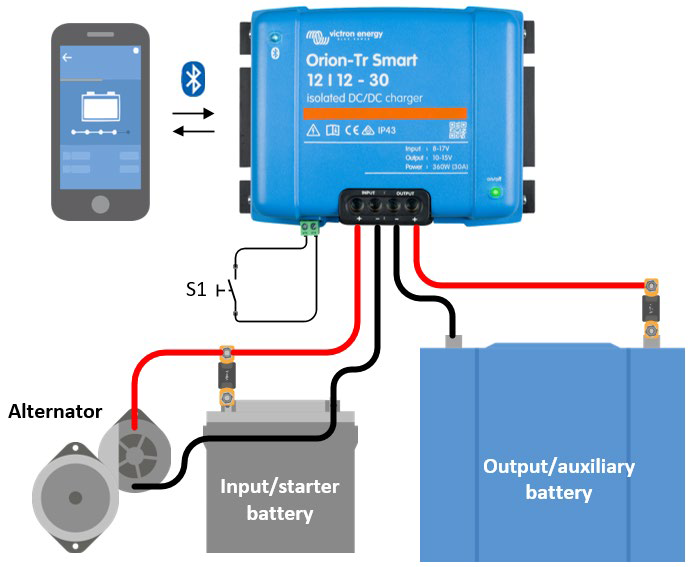
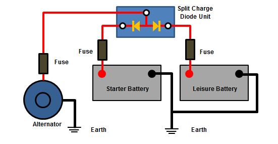
Engage a qualified professional if needed. Battery charging also gives you the opportunity to inspect and replace if necessary damaged cables or batteries. Blue sea two battery switch acr dual charging system. Battery switches twin alternators split charge diodes and vsrs. While charging the bluesea charging relay and the newmar battery integrator automatically connect all banks. An understanding of basic boat wiring.
Most boats these days have at least two batteries on board and for good reason. The boater just has to plug in the shore power to charge no flipping battery. Your boats batteries are a cornerstone of a good. For more detailed wiring guidelines please consult a qualified marine electrician or one of the many books available on the subject. To begin taking the right steps to achieve a good electrical system on your boat you need to. Each ah we deliver to the battery at a high soc is not being stored at 100 or even 50 due to.
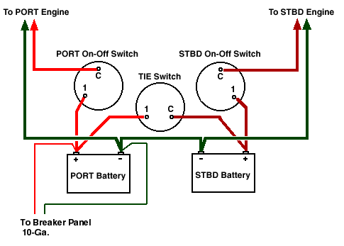
See the electrical diagram for details while discharging the batteries each bank is isolated so a bad battery will not completely drain the other two banks. Provide adequate power storage and starting capacity. Despite being minimally depleted it still takes a good bit of time to reach an actual 100 soc again. Heres a brief guide to them. Boat dual engine battery diagram boat dual engine battery diagram project add a battery house and start batteries when the boat is underway and also while at the dock or driveway when connected to a charger in the unlikely event you need to use your house battery to start your engine turn the dual circuit plus battery switch to the combine batteries position this will combine the batteries for engine starting add a battery battery switches installation and operating see diagram 2. Things have come a.
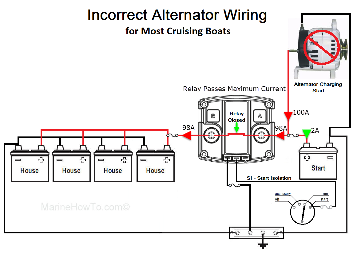
Be sure that all safety requirements such as the relevant abyc standards are met. Items you will need. Please understand that even if you feed charging to the start battery first which is not advised on a cruising boat with disparately sized banks 30 seconds of charging is not charging even for a minimally depleted start battery. If your charger is small enough to be carried aboard your boat you can leave these cables in place since the charging procedure requires it. Any discussion with a marine technician will highlight the fact that often times a boats operational problems are related to its electrical system. Determine your power requirements.
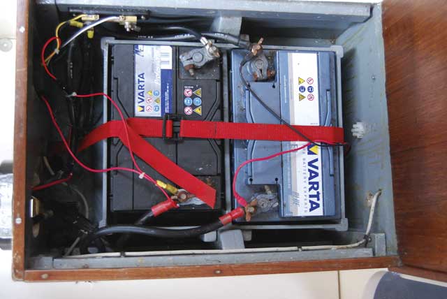
Two battery boat setup with wiring diagram. Be sure your wiring is adequate and approved for marine use and connections are sound. A battery at 99 soc is in the worst range of charge efficiency.

