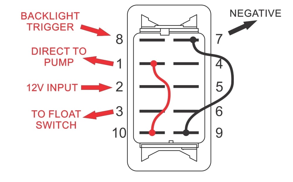
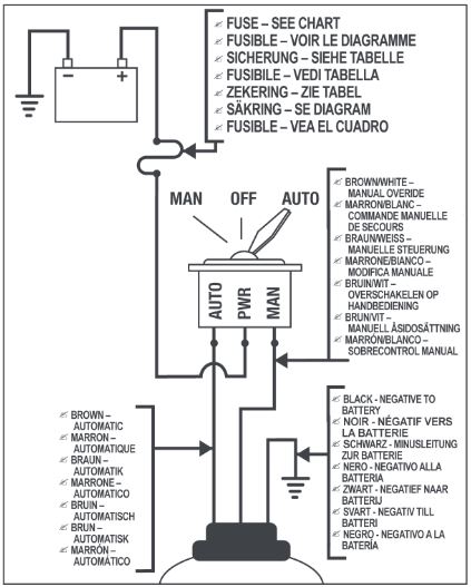
Including wiring diagram further simplify installation. Ultima switch electronic automatic switch part no.

Wiring A Bilge Pump In A Boat
Bilge pump brown wire. Main menu find the right fit. Pump will continue cycling and drain batt. With ignition on pump cycles on every 4 5 mins. Shoreline 3 way bilge pump switch panel makes wiring your bilge pump system as easy as it gets. The boat had three wires. Seems the float is not working as i checked it for continuity but i jumped through the plug that the float connects to and still not working.
So if youve ever. The pump has two wires hot brown and ground black. If a second bilge pump is to be monitored connect the gray wire pin 6 gray connector to the positive side of the bilge pump 2. Thats why brown wires to ignition on. Question about bilge pump functionality. The previous auto feature didnt work so i bought a new pump.
My mayfair livewell pump has a brown and black wire. The pump also has 3 wires. Brown and white wires for bilge got a multimeter or a test light. Shoreline 3 way bilge pump switch panel makes wiring your bilge pump system as including wiring diagram further simplify installation. For use with all 12 vdc systems. Black brown and brown with a red stripe.
If bilge pumps are to be monitored connect bilge pump 1 via the blue wire pin 1 gray connector to positive side of pump 1. Troubleshooting bilge pump wiring to find out why bilge pump not working. Verified pump works by applying 12v direct to motor. Some bilge pumps round ones that have 3 wires are automatic pumps. Also verified that there was 12v coming into the plug that connects to float. Now believe that i understand what was happening as i think the toggle switch for on for the.
You will need to provide power to the other side of the manual switch 4. Chief petty officer join date. If hooked straight to batt. My last boat had a rocker switch on the dash if you. Guys i am putting my boat back together and i noticed my rule bilge pump has a brown and white wire. Brownwhite to dash switch.
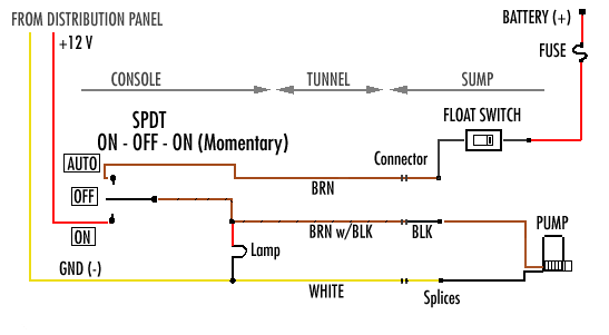
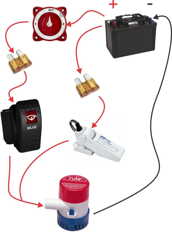
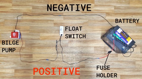
Mar 31 3 the brown wire from the float switch connects to both the brown wire on the bilge pump and the 2nd 12vdc source from manual switch they show. Brown wire to ignition on hot wire. High water detection optional additional parts are required if a high water detection is required connect the orange wire pin 7 gray connector to the ground side of the fb sentry high waterfloat switch part sw0052. The diagrams show conection of brown pump wire to float switch and an intemediary. Jeff and i thought lets do a quick video. A bilge pump b ball float switch c dc supply d panel e brown wire pump f black wire pump electrical installation with the spx flow johnson pump panel always install according to the wiring diagram.
So is that the same for the bilge or is white positive. Hi all im installing a new automatic bilge pump in my 1999 sslxi. And it does have some kind of switch or small itty bitty float so if its submerged it come on. On occasion well get a customer asking us where the three wires go when installing a rulemate or rule computerized bilge pump. At that point it has a float switch and will only run if water fills up in the bilge. I just wired it up but the new pumps auto feature isnt working either.
July 10th 2008 0455 pm. Check each across a known black ground with the test. I know on my live well that brown is positive. Am i correctthe bilge pump needs to be turned on powered by the rocker switch on the dash. Surprisingly i found both pins had 12v to ground.
