As the liquid level in the tank drops to the lower limit ll as shown in figure a. This diagram is for the circuit to empty a tank using two normally open float switches and a two pole changeover relay.
Choosing Your Pump Configuration Single Vs Three Phase
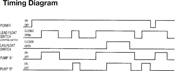
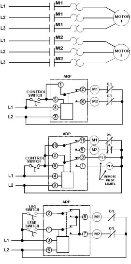
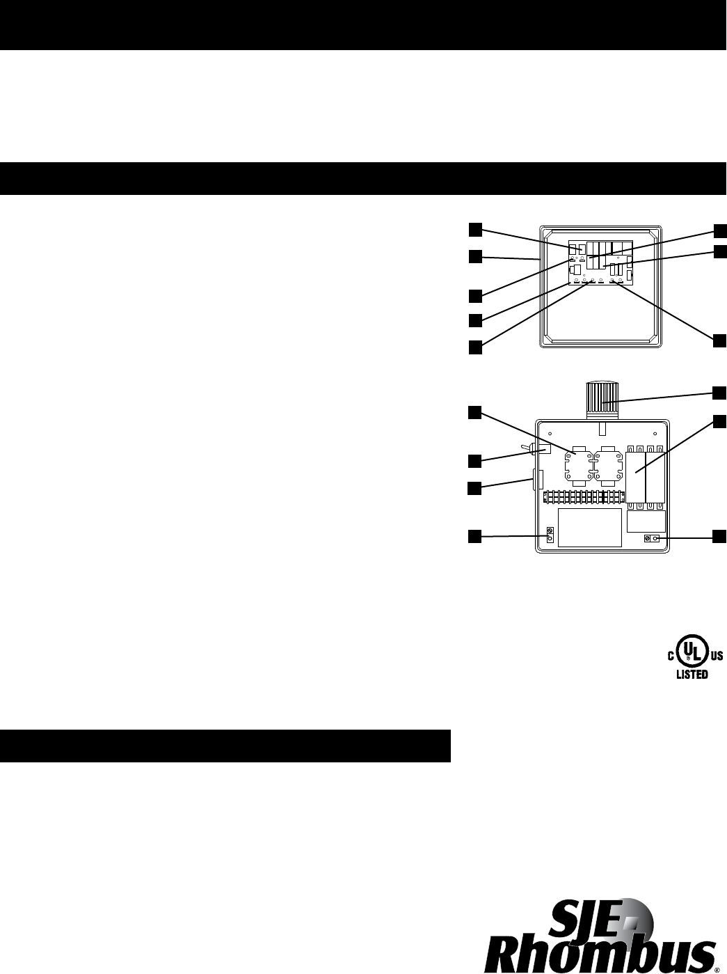
Alternating pump control schematic. Closing the toggle switch sw will place the control circuit ready for operation. Bulletin 700 hta alternating relays serve as interposing relays between your controller and field devices. The control panel has an alternating relay that switches between pump 1 and pump 2 after every cycle during automatic operation. Installation scenarios might include a normally open float switch turning on a pump to empty a tank control schematic 2 or a normally closed float switch turning off a pump that fills a tank control schematic 1. When the control switch opens load 2 is turned off the alternating relay toggles back to the load 1 position the red led marked load 1 is on and the process can be repeated. Pump 1 will remain operational until the stop float opens.
The next time the stop and lead floats are closed the alternating circuit will energize pump 2 and the pump 2 pump run light will illuminate. Figure b illustrate the schematic diagram of the control circuit of the alternate operation of a two motor pump. The float switch contact fs 1 2 will close see figure b. A dpdt alternating relay is the same as a spdt but with an extra set of no nc contacts. You can use these relays in applications with pumps compressors air conditioning and refrigeration units. Using the counter chip.
A cmos seven stage ripple counter cd4024 can be used to build a simple alternating relay. In this circuit the relay will change state each time the control switch opens. The relay will be held in the energised state until the bottom. The bottom switch will be closed provided the liquid is above that switch point. Pump 2 will remain operational until the stop float opens. This means that once the liquid level reachs the pump on float that pump 1 will run until the liquid level reachs the pump off float.
In both schematics terminal 1 in the control circuitry represents the landing point for the float switchs wire and terminal 2 for the wire. Mount or suspend your. When the control switch closes again it energizes load 2. A two wire float switch that can easily be used for turning a pump on or off. So there we have it. One set of relay contacts connects the pump to the supply and the other maintains the relay on state while the level falls towards the bottom switch.
The d85 series of alternating relays are used with one control switch per device and are available in standard 8 pin or 11 pin footprints with either spdt or dpdt output configurations with or without a three position selector switch which allows the unit to alternate the two loads as normal or lock the relay to one load or the other. The alternating feature lets you select the primary or secondary load or to alternate between the two. The liquid rises until the top float switch closes and energises the relay. In this video we will look at a physical pump panel along with its schematic and we will explain what each of the components does and how they are wired. In the last video in this series we went.
Gallery of Alternating Pump Control Schematic