W2 cj2 ui vi wi w2 cj2 ui vi wi a cow voltage y high voltage z t4 til t12 10 til t4 t5 ali l2 t12 ti blu t2 wht t3org t4 yel t5 blk t6 gry t7 pnk t8. These windings have no electrical connection for starting but uses induced current to make a rotating magnetic field.

6 Pole Wiring Diagram H1 Wiring Diagram
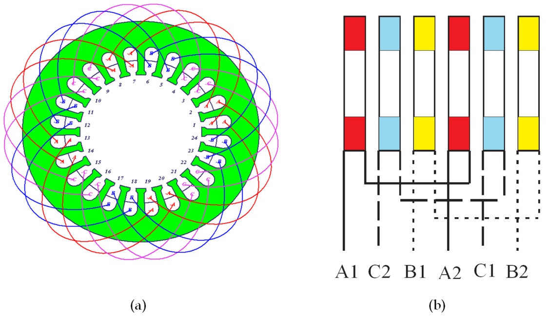
6 pole motor wiring diagram. The diagram for your application is figure 3. Dec 30 ive attached a page from the square d motor control wiring diagram book that has the diagram for a 6 pole reversing drum switch which is a universal application so the diagrams also apply to your dayton switch. The stator poles are equipped with an additional winding in each corner called a shade winding as shown in fig4. The motor will supply the same amount of power but with a different load amperage. Reverse baldor single phase ac motor circuit diagram duration. 3 phase 6 pole motor wiring diagram wiring diagram is a simplified pleasing pictorial representation of an electrical circuitit shows the components of the circuit as simplified shapes and the capacity and signal links amongst the devices.
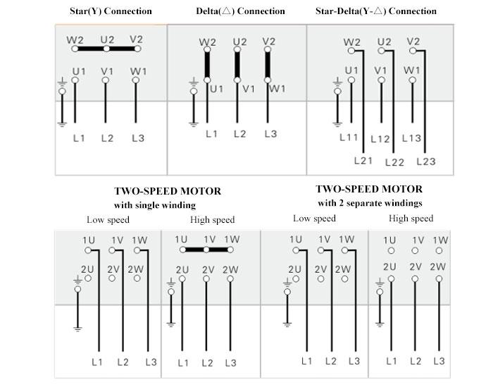
Always use wiring diagram supplied on motor nameplate for motors without thermal protection single voltage single rotation single voltage reversible rotation dual voltage single rotation split phase motor dual voltage reversible rotation capacitor motor single phase wiring diagrams always use wiring diagram supplied on motor nameplate. How to wire a furnace or ac blower motor duration. How the wires are interconnected dictates the voltage being supplied to the motor. 3ø wiring diagrams 1ø wiring diagrams diagram er9 m 3 1 5 9 3 7 11 low speed high speed u1 v1 w1 w2 u2 v2 tk tk thermal overloads two speed stardelta motor switch m 3 0 10v 20v 415v ac 4 20ma outp uts diagram ic2 m 1 240v ac 0 10v outp ut diagram ic3 m 1 0 10v 4 20ma 240v ac outp uts these diagrams are current at the time of publication. Carvetools 100268 views. The higher the voltage the lower the.
A copper conductor isolates the shaded portion of the pole. May 7 2018 36 slots 3 phase 6 pole induction motor rewinding diagramfullhd youtube. It shows the components of the circuit as simplified shapes and the aptitude and signal associates amongst the devices. 6 pole motor wiring diagram wiring diagram is a simplified good enough pictorial representation of an electrical circuit. Six wire three phase electric motors are dual voltage motors. Word of advice tv 101648 views.
The pole structure of the shaded pole motor enables the development of a rotating magnetic field by delaying the buildup of magnetic flux. Stepper motors with these center taps are often referred to as unipolar motors. A 6 wire stepper motor is similar to a 4 wire configuration with the added feature of a common tap placed between either end of each phase as shown in figure 2. Wiring a single phase volt motor is. Shaded pole motor wiring diagram. This wiring configuration is best suited for applications requiring high torque at relatively low speeds.
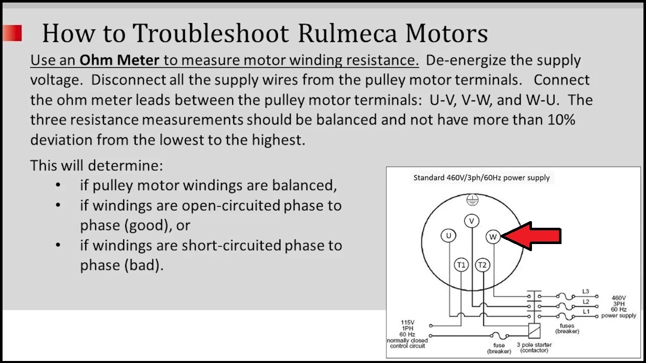
The supply voltage is either 240 volts alternating current vac or 480 vac.


