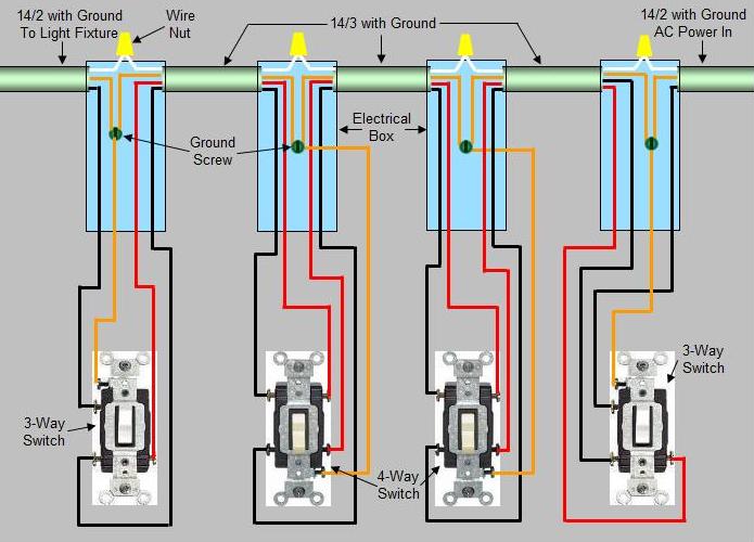
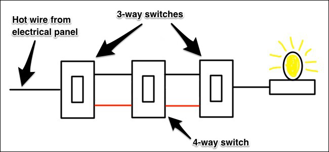
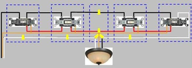
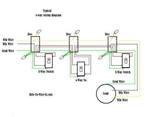
A four switch configuration will have two 3 way switches one on each end and two 4 way switches in the middle. 4 way switches have four terminals each with two pairs of travelers one set usually black and one set usually brass color.
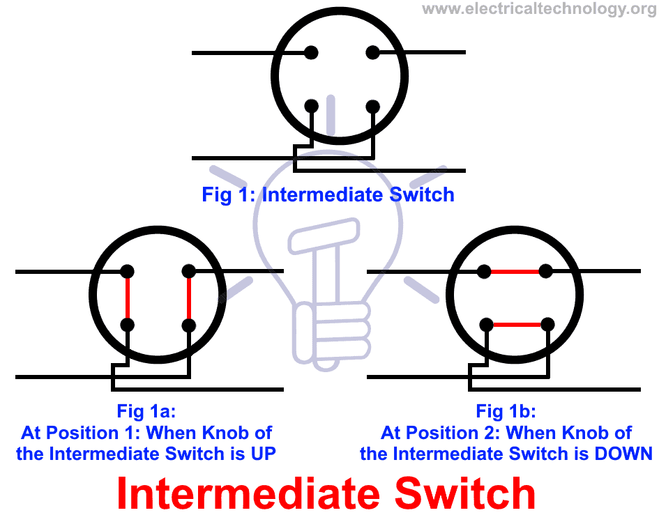
Intermediate Switch 4 Way Switch Construction Working
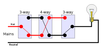
4 way switch circuit. A 4 way switch has two positions. If more than three switches are needed simply place more 4 way switches between the three way switches. The circuit neutral is spliced at each switch box through to the light fixture using the white wire. License creative commons attribution license reuse allowed show more show less. In the first position the contacts are connected straight through so that the switch has no effect. Wiring a 4 way switch is simply adding a switch to an already existing 3 way switch circuit.
In the diagrams below the first switch 3 way common terminal connects to line voltage. In this basic 4 way light circuit 3 wire cable runs between all the switches and 2 wire cable runs from the last switch to the light. I have a few of the most common ways in wiring a 4 way switch to help you with your basic home wiring projects. Turn on the light or device being controlled by the 3 way switches if you already have them. A 4 way switch wiring diagram is the clearest and easiest way to wire that pesky 4 way switch. Starting with safety and understanding 1.
The electrical source is at the first 3 way switch and the hot wire connects to the common there. There are two conduits coming into each electrical box for the 4 ways. If the device is still. Red black white wires. Return to location you plan to wire to verify that there is no electric flow to that device. 4 way switches provide switching from three or more locations.
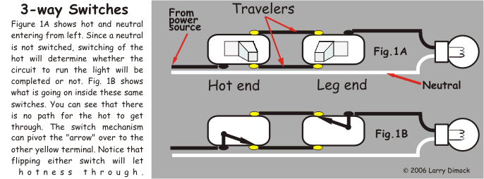
First of all we need to go over a little basic terminology on switches. This video walks through how to solve a for the number of wires in a 4 way switching circuit. As you will see most 4 way switch wiring is placed between the wiring of two 3 way switches therefore a 4way switch is installed with two 3way switches. The red and black wires were connected to the 4 way switches and the whites tied together. Turn off electric power. To try and make the circuit simpler i decided to bypass all the 4 ways.
This allows you to control a load from other locations in addition to the 2 locations that a 3 way circuit provides. In position two the switch cross connects the contacts on the left with the contacts on the right in an x connection.


