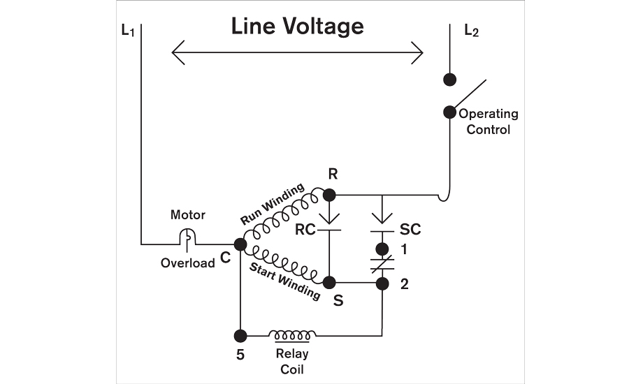
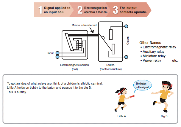
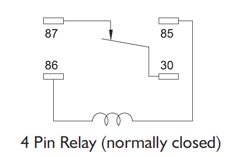
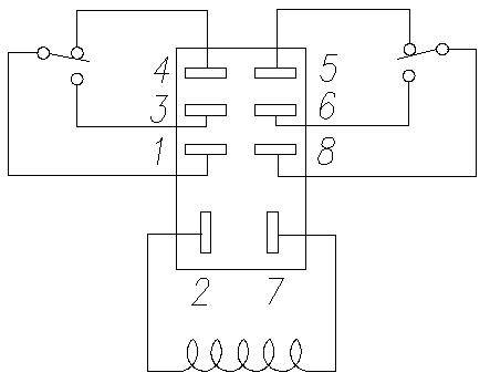
Wiring diagram relay starter motor fresh ignition relay wiring. Here is a video on how you can test a relay with or without a diagram.
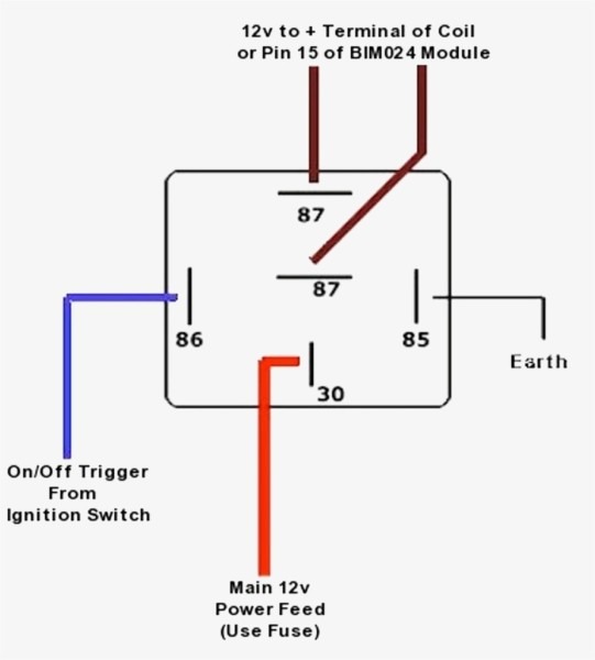
12 Volt Relay Wiring Diagram 4 Pole H1 Wiring Diagram
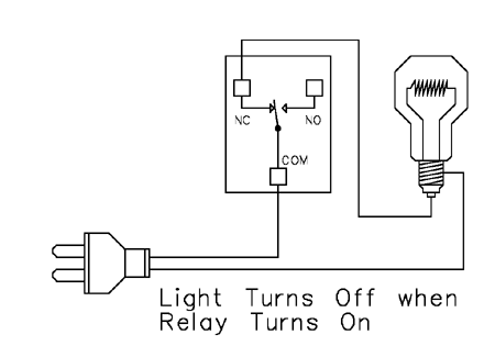
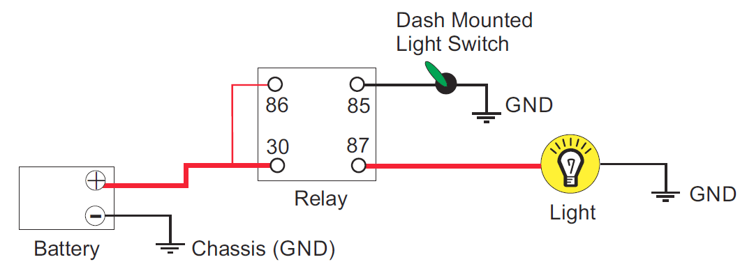
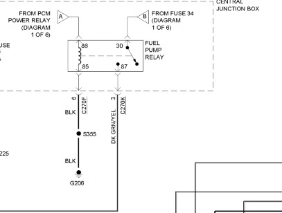
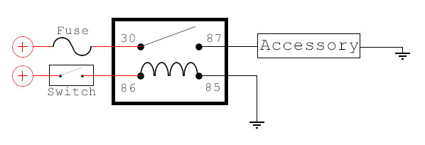
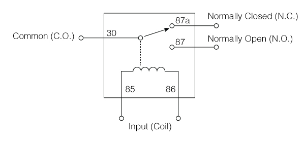
4 terminal relay diagram. When a relay is off the common is connected to the nc normally closed. 4 pin relay 4 pin relays use 2 pins 85 86 to control the coil and 2 pins 30 87 which switch power on a single circuit. Wiring diagram starter solenoid refrence elegant 4 pole solenoid. 12v 40a relay 4 pin wiring diagram. Collection of 4 pole starter solenoid wiring diagram. A wiring diagram is a streamlined conventional pictorial representation of an electrical.
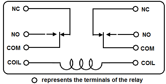
Iii double pole single throw dpst such relay has 6 terminal pins which consist of a pair of coil pins and two pairs of pins where pins in each pair can be made connected or disconnected by activating or deactivating the relay. Wire connectors quick splices. The real benefit behind a relay is more than automation. A 4 terminal relay is used so a low power circuit may engage a high power circuit without risk of damage to the low power control circuit. Uxcell black dc 12v 40a 4 pin terminal spdt relay for car automotive. 4 pole starter solenoid wiring diagram.
The relay features a plastic housing with mounting tab for easy installation. 12v relay 4 pin automotive 40amp 40a changeover ry15 normally open. The purpose of a relay is to automate this power to switch electrical circuits on and off at particular times. They also provide the ability to switch multiple circuits including different voltage. Such relay is actually a combination of two spst relay structures with only one coil pin pair. The no normally open connection of the relay is not connected until the relay turns on.
Automotive relay diagram. 4 pole solenoid wiring diagram download. I cover 34 and 5 pin relays and all you need is a 12v source a multimeter and a test light. For example a low power circuit in a car that commands the high power headlights to come on would send the command through a 4 terminal relay. All examples shown are for spdt single pole double throw relays which includes any of the 5 10 or 20 amp relays on this site. Relay logic the com common connection of a relay is the part of the relay that moves.
There are 2 types of 4 pin relay available. Free wiring diagram menu. Diagrams will show how multiple relays one relay or another or just one relay can control your device. The terminal widths used on 4 and 5 pin relays are almost always 63mm wide however some more specialist relays can have terminal widths of 28mm 48mm and 95mm. Free download with regard to 12v 30 amp relay wiring diagram by admin from the. Relays are switches controlled by electrical power like another switch computer or control module.
The 95mm wide terminals tend to be used for higher power applications such as for starter motor solenoid activation and the smaller terminals tend to be used for electronics signalling where only very low currents are required. All widths will be compatible with the standard female blade crimp terminals of the corresponding. September 3 2018 july 26 2018 by larry a. The difference between a 4 and 5 pin relay is that a 4 pin relay is used to control a single circuit whereas a 5 pin relay switches power between two circuits.


