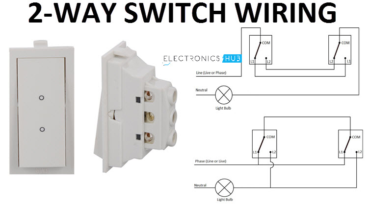
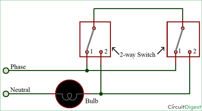
How is it possible for a two wire control circuit to control the operation of a three phase motor. The l1 terminals of both the switches are connected to line or phase or live of the ac supply.
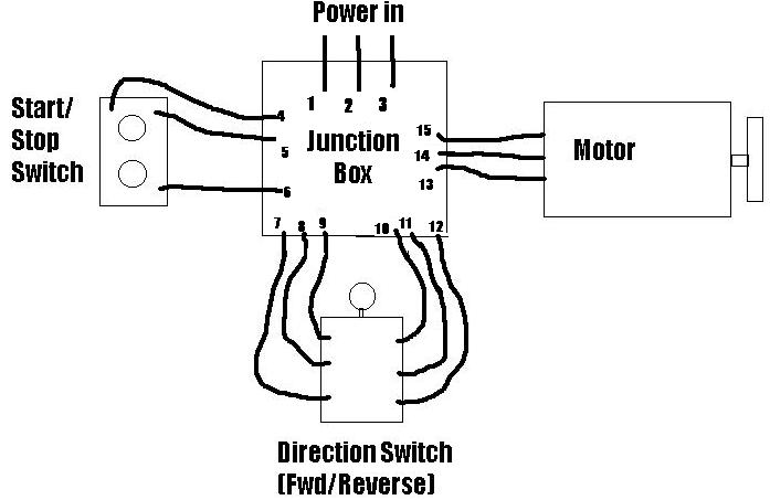
3 Phase Wiring Question Start Stop Switch The Home Machinist
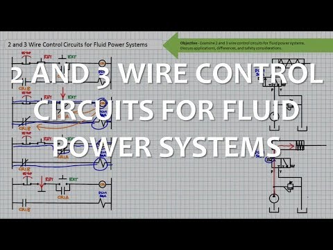
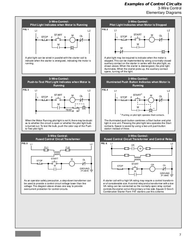
3 wire control circuit. Line diagrams also called schematic or elementary diagrams show the circuits which form the basic operation of the controller. Line diagrams show circuits of the operation of the controller. These circuits are characterized by their usage and electrical power limitation which differentiates them from light and power circuits. Control wiring 3 wire control start stop circuit the most common use of 3 wire control is a startstop control. The l2 terminals of both the switches are connected to one terminal of the light bulb while the other terminal of the light bulb is connected to neutral. Figure 3 right shows a more complex two wire control circuit that is used to control an air compressor.
Class 1 2 and 3 circuits are classified as remote control signaling and power limited circuits in the national electrical code nec. This circuit is still a two wire control circuit andits used to turn the air compressor on automatically when the pressure drops below 30 psi and to turn off the compressor when the pressure reaches 90 psi. Refer to the schematic shown in figure 184. They can be used as a guide when wiring the controller. The first way of wiring uses a couple of two way light switches with a 3 wire control. This is a 3 wire control circuitdraw a circuit which is controlled by a handoffautohoa switch in the hand position a motor with overload protection which is connected to a fan will be controlled by a start button a stop button and a holding contactin the auto position the motor will be controlled by a temperature switch an increase in temperature.
What type of switch is the thermostat. Here is the complete guide step by step. Ladder diagram basics 3 2 wire 3 wire motor control circuit duration. The nec defines such circuits as that portion of the wiring system between the load side of the overcurrent protection device ocpd or the power limited supply and all connected equipment. Basic control circuitsthree wire control circuits 1. In both circuits shown above the reverse command can be ignored if not necessary for the application still the same circuit is applicable for 2 wire and 3 wire control.
Pressure switch a in this. Electric motors troubleshooting and understanding w tpc online webinar tpc. You can observe in the schematic that both the com terminals are connected together. These circuits are also. Pete vree 331110 views. They show the relative location of the components.
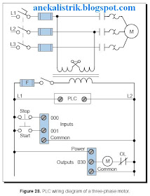
The following is the simple schematic of a three wire 2 way switch wiring. Single phase submersible pump control box wiring diagram 3 wire submersible pump wiring diagram in submersible pump control box we use a capacitor a resit able thermal overload and dpst switch double pole single throw. What are the two major types of control circuits. The wiring connection of submersible pump control box is very simple. Figure 1 is a typical wiring diagram for a three phase magnetic motor starter. Notice that the wiring diagram for the control and load circuit is shown in figure 3a and the ladder diagram of the control circuit is shown in figure 3b.
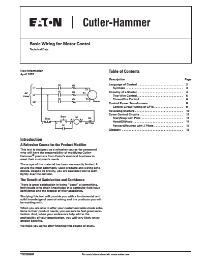
Basic wiring for motor control technical data. See image below for an example of 3 wire control being used to pull in a contactor to start a 3 phase motor. It means if the stop command is provided separately it is called 3 wire control and if separate stop command is not provided separately it is called as 2 wire control. Figure 1 typical wiring diagram. They do not.
Gallery of 3 Wire Control Circuit