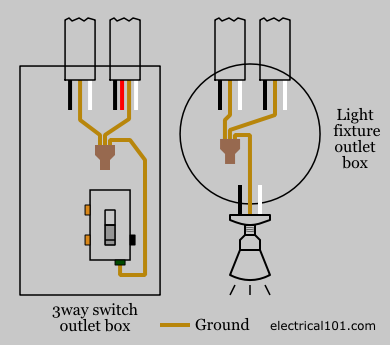
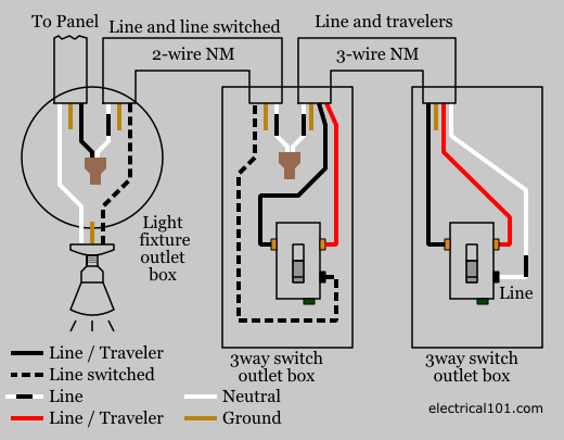
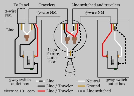
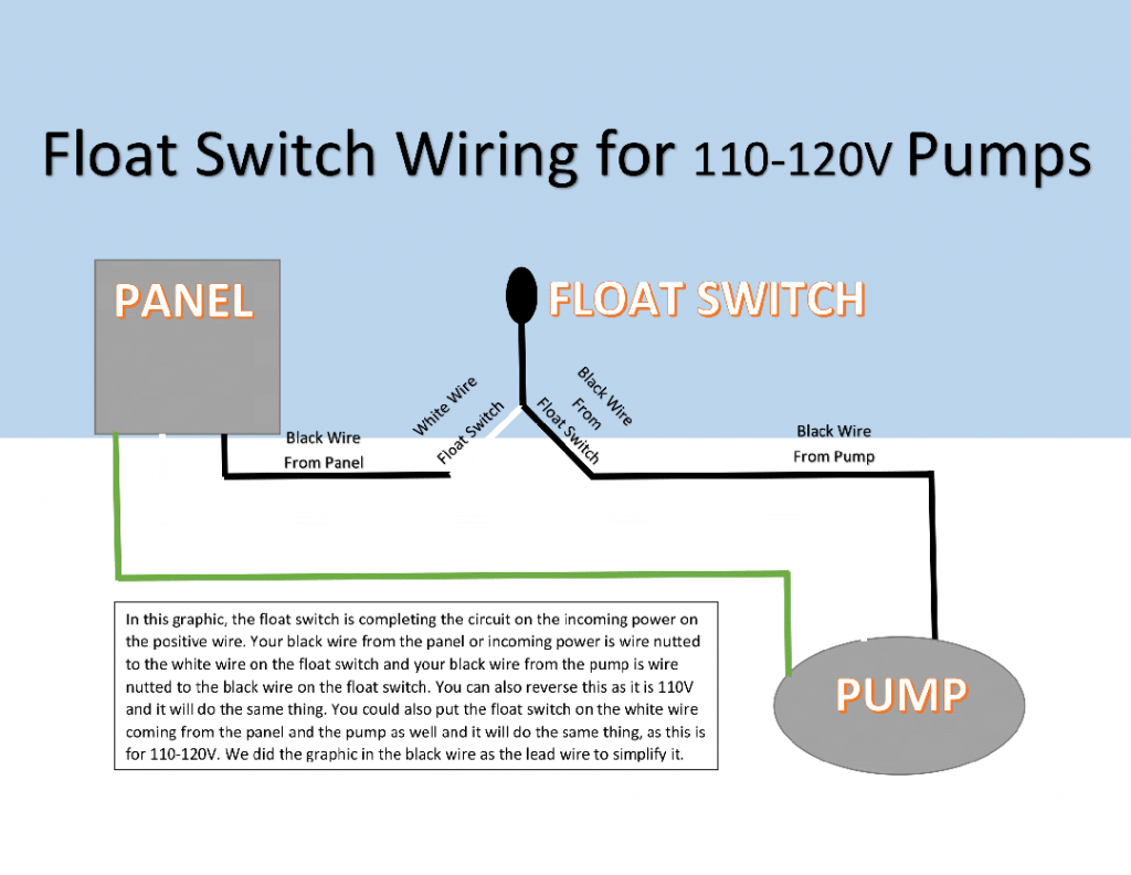
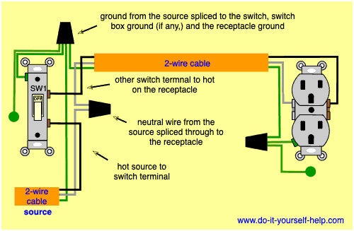
The source is at sw1 and 2 wire cable runs from there to the fixtures. Variety of lighted rocker switch wiring diagram 120v.

71054 Magnetic Paddle Switch 120v
120v switch wiring diagram. Each part should be placed and linked to different parts in particular manner. A wiring diagram is a simplified traditional photographic representation of an electrical circuit. Otherwise the arrangement wont function as it ought to be. Illuminated rocker switch wiring diagram 120v illuminated rocker switch wiring diagram 12v illuminated rocker switch wiring diagram 240v illuminated rocker switch wiring diagram every electrical structure consists of various diverse pieces. To reverse rotation on a single phase capacitor start motor you will. Connect the marked white wire to the black lead going to light.
Lighted rocker switch wiring diagram 120v elegant amazing lighted. 120v ac capacitor motor reversing switch wiring diagram. 26102018 26102018 0 comments on 120v ac capacitor motor reversing switch wiring diagram. Mark the extension wires with colored tape to identify switch wires both ends. Dimmer switch wiring diagram. It shows the parts of the circuit as streamlined shapes and the power as well as signal connections in between the devices.
Lighted rocker switch wiring diagram 120v download. To complete a single phase motor direction change you will need to motors go in forward and reverse depending on their wiring and the resulting magnetic field. Otherwise the structure will not work as it ought to be. Fiber optic cable electrical connections boundary seal to be in. Wait to connect the marked black wire going to switch. Toggle switch wiring diagram unique luxury lighted rocker switch.
Each component ought to be placed and linked to different parts in particular manner. A wiring diagram is a simplified traditional pictorial depiction of an electric circuit. It reveals the parts of the circuit as streamlined shapes and the power as well as signal connections between the devices. If not the arrangement wont work as it should be. Change fixture to desired style and connect the neutrals white and ground wires bare or green. The hot and neutral terminals on each fixture are spliced with a pigtail to the circuit wires which then continue on to the next light.
A rheostat or dimmer makes it possible to vary the current flowing to a light fixture thereby varying. 4 way switch wiring diagrams do it yourself help within 120v electrical switch light wiring diagrams image size 502 x 330 px and to view image details please click the image. Lighted rocker switch wiring diagram 120v 120v illuminated rocker switch wiring diagram lighted rocker switch wiring diagram 120v every electric arrangement is composed of various diverse parts. Top 25 best electrical wiring diagram ideas on pinterest intended for 120v electrical switch light wiring diagrams image size 500 x 523 px and to view image details please click the image. To be able to be certain the electric circuit is constructed properly. Reversing single phase induction motors.
Run a two conductor wire to a switch in a desired location and install electrical box with switch. Single phase motor wiring diagram with capacitor baldor single phase motor wiring diagram with capacitor single phase fan motor wiring diagram with capacitor single phase motor connection diagram with capacitor every electrical arrangement is made up of various unique pieces. Ask that they not flip any breakers or switches until you are finished. Collection of 120 volt relay wiring diagram. How do i install a 120v single pole switch when the light box has power to it. This is the simplest arrangement for more than one light on a single switch.
Wiring diagram book a1 15 b1 b2 16 18 b3 a2 b1 b3 15 supply voltage 16 18 l m h 2 levels b2 l1 f u 1 460 v f u 2 l2 l3 gnd h1 h3 h2 h4 f u 3 x1a f u 4 f u 5 x2a r power on optional x1 x2115 v 230 v h1 h3 h2 h4 optional connection electrostatically shielded transformer f u 6 off on m l1 l2 1 2 stop ol m start 3 start start fiber optic transceiver class 9005 type ft fiber optic push button selector switch limit switch etc. This diagram illustrates wiring for one switch to control 2 or more lights. Each component should be placed and linked to different parts in specific way.
