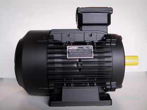
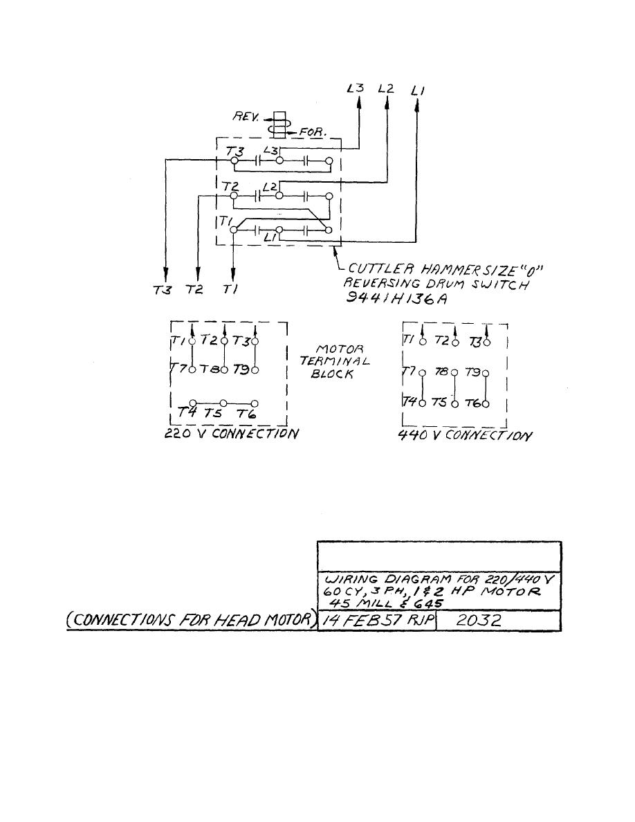
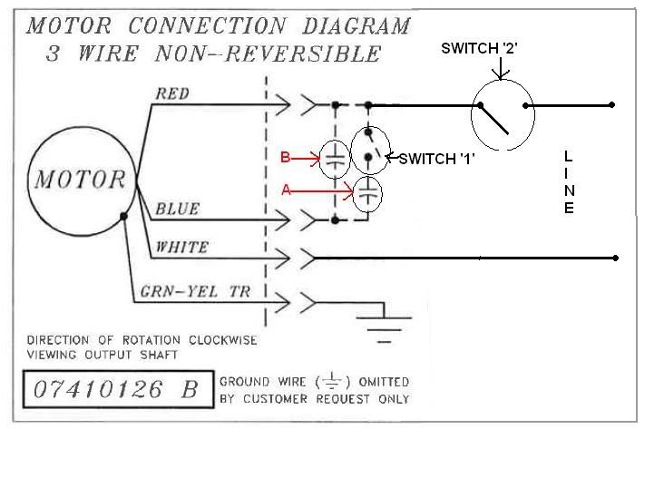
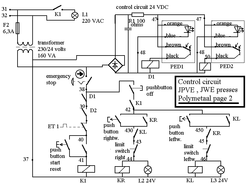
The lafert group is a leading european motor company that has built a reputation for the manufacture of customised electric motors and drives. Lafert motor wiring diagram.

Lafert Wiring Diagram Diagram Base Website Wiring Diagram
Lafert motors wiring diagram. Italian made iec motors gear reducers and speed variators are all part of our stock items. He amh st am wiring diagrams additional wiring diagrams are also available please enquire 2 pole motors 4 pole motors now available 315 frame sizes please enquire st range he range. And upwards diagram dd5 two speed motors for all other single phase wiring diagrams refer to. See page 19 for dve motor list. Focused on the areas of industrial automation energy saving and wind power the group is strongly oriented toward technological innovation. The af and ambz models are furnished with three phase brake coils with a separate terminal block in the connection box to power the brake.
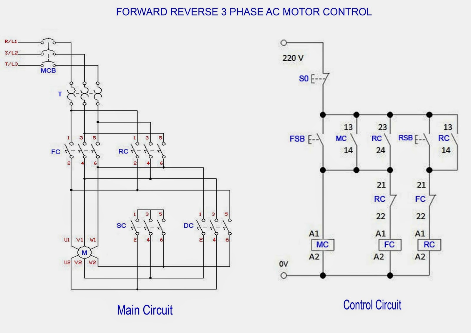
It is important to note that if the motor and brake coil are to be wired together to operate or stop at the same time the power should be brought to the motor block first and then connected to the brake coil to avoid the. It shows the components of the circuit as simplified shapes and the faculty and signal links together with the devices. As with the brushless permanent magnet servo motors the rotor of the lafert hp motor has no losses. With the target to improve performance while reducing environmental impact energy efficiency and product customisation to meet individual customer requirements are fundamental. 16092018 16092018 4 comments on lafert motor wiring diagram. Part number frame size hp weight lbs full load amps 115v run cap 115v lme start cap 115v lme current relay 115v full load amps 230v run cap 230v.
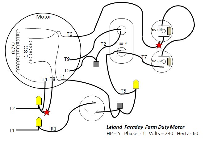
36 the range of energy efficient motors from lafert is the first complete range of ie2 and. Lafert motor wiring diagram. Dve motors feature capacitor start and run making them suitable. Lafert motor wiring diagram wiring diagram is a simplified enjoyable pictorial representation of an electrical circuit. Wiring diagrams standard motors m 3ø wiring diagrams 1ø wiring diagrams m 3 m 3 high speed delta connection low speed star connection w2 or white w2 or white u2 or black u2 or black v2 or orange v2 or orange u1 or red u1 or red v1 or yellow v1 or yellow w1 or blue w1 or blue thermal contacts tb white thermal contacts tb white l1 l1 l2 l2 l3 l3 e e codes. Always use wiring diagram supplied on motor nameplate for motors without thermal protection single voltage single rotation single voltage reversible rotation dual voltage single rotation split phase motor dual voltage reversible rotation capacitor motor single phase wiring diagrams always use wiring diagram supplied on motor nameplate.
W2 cj2 ui vi wi w2 cj2 ui vi wi a cow voltage y high voltage z t4 til t12 10 til t4 t5 ali l2 t12 ti blu t2 wht t3org t4 yel t5 blk t6 gry t7 pnk t8. Lafert north america is keeping up to date with all covid 19 developments surrounding the pandemic and following all applicable canadian government canadian public health cdc centers for disease control who world health organization guidelines and regulations while doing our part to contain the spread of the novel coronavirus. Metric motor lafert north america is the leading supplier of metric motors in canada usa and mexico. Ms three phase motors. Over 90 of the units produced are. Single phase motor capacitor start run connection diagrams single dual voltage to change direction of rotation switch lead a with lead c dve motors are designed for high starting torque applications.
The health and safety of our staff customers and partners is our top priority and we are working hard to ensure that all risks involved are minimal. See the below diagram for derating of output current versus altitude at ta max.

