Workers use these documents to install systems on site. Solidworks electrical comes pre packaged with device libraries containing thousands of symbols 2d footprints and manufacturer parts.

How To Read Circuit Diagrams 4 Steps Instructables
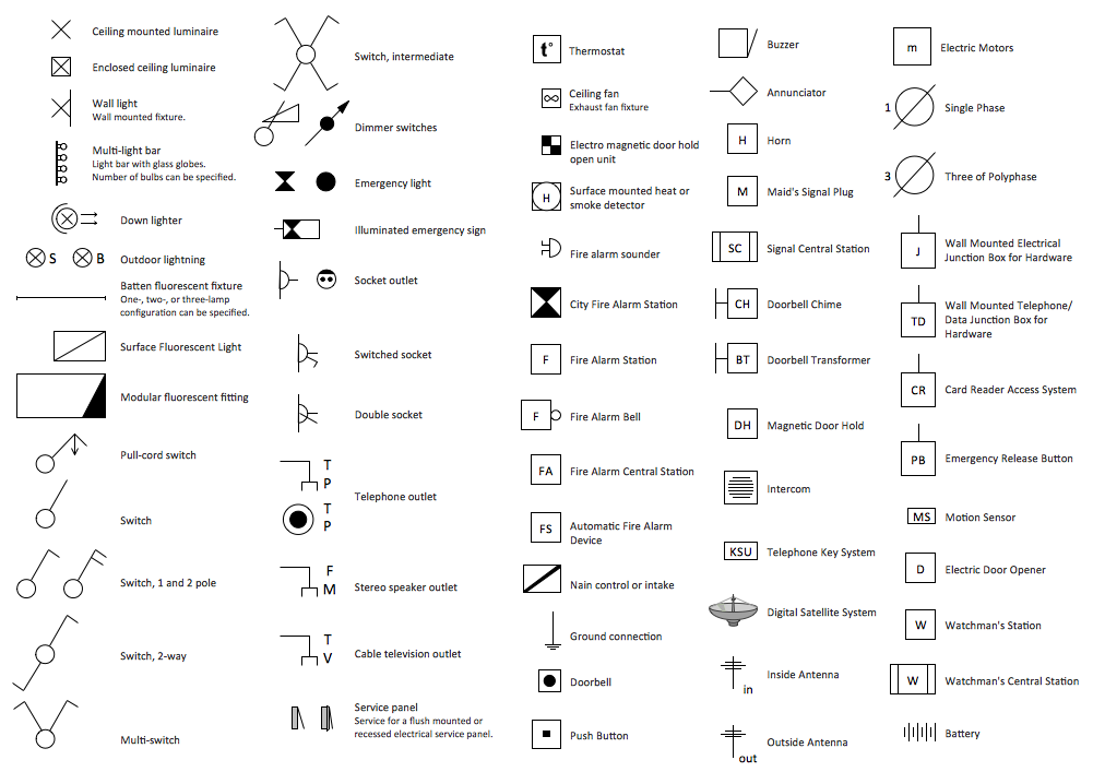
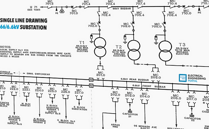
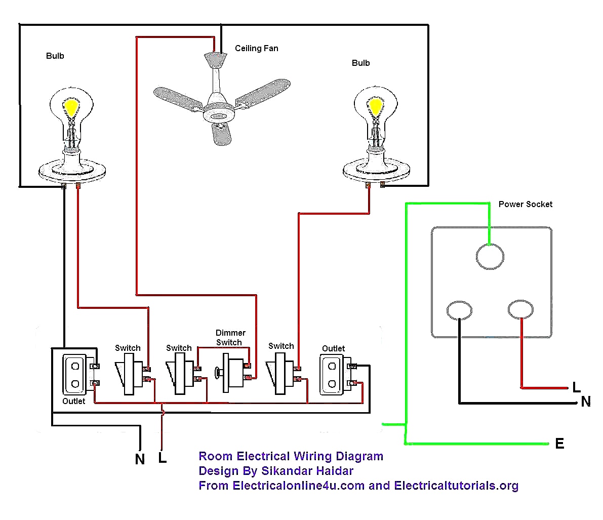
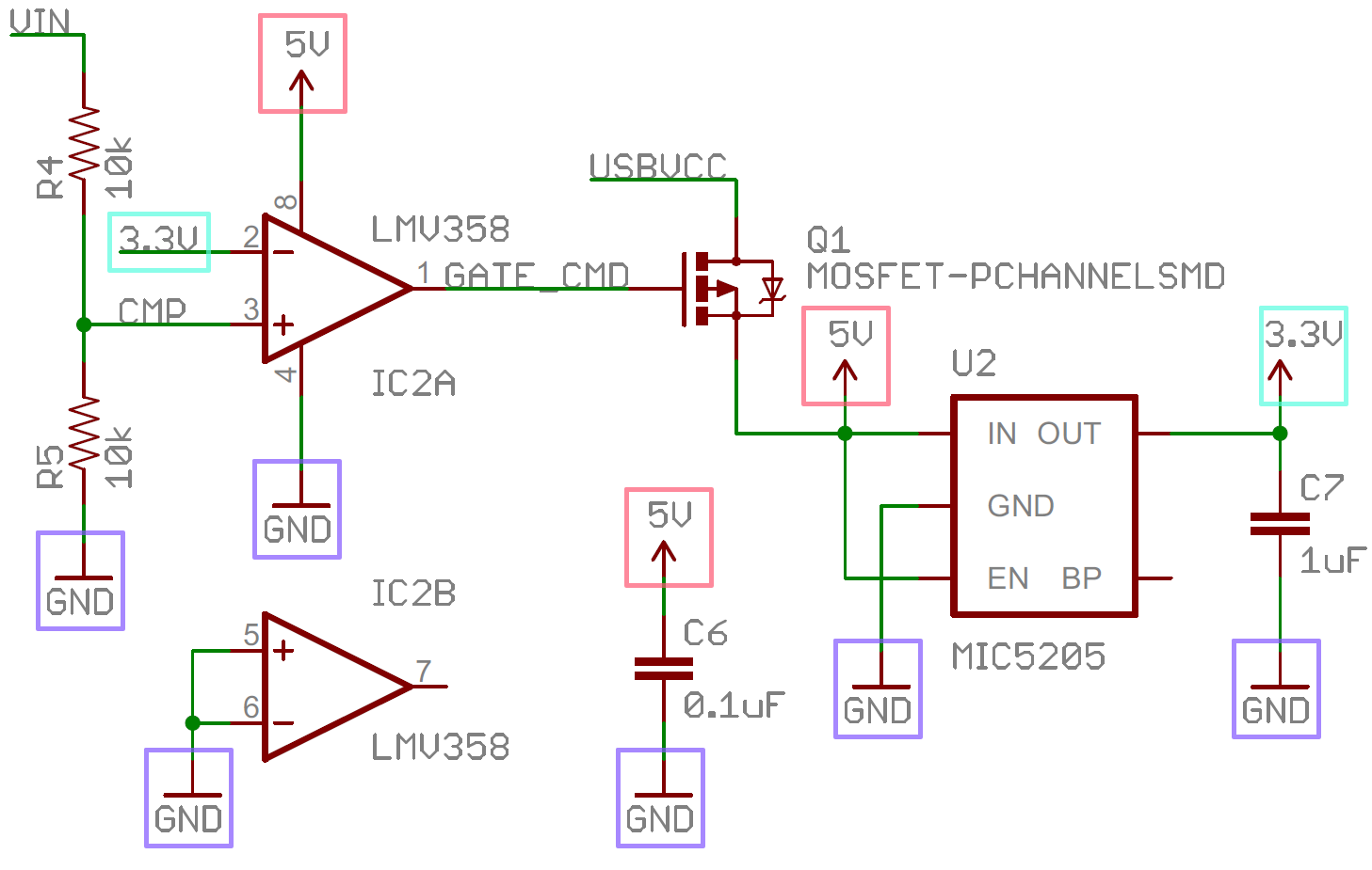
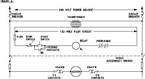
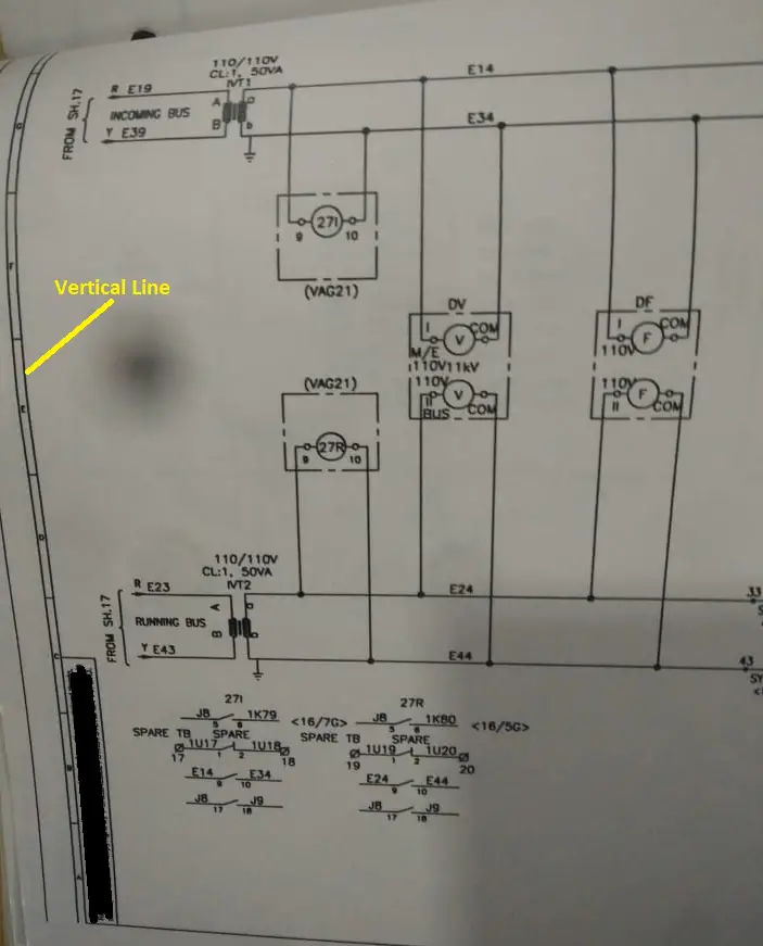
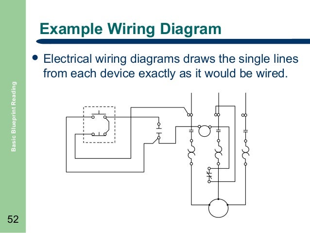
How to read electrical drawing. No doubt there are many circuit symbols left off this list but those above should have you 90 literate in schematic reading. Electrical drawings are technical documents that depict and notate designs for electrical systems. What is an electrical drawing. A drawing of an electrical or electronic circuit is known as a circuit diagram but can also be called a schematic diagram or just schematic. Capacitors have different types that are in common use. Lets start with 10 simple questions.
Our scope of services residential commercial industrial etc all solution estimation construction solution structural design architectural plan detail engineering assessment electrical drawing plumbing drawing retrofitting rajuk plan. Beginners guide how to read electrical schematics 1. In order to learn how to read a circuit diagram it is necessary to learn what the schematic symbol of a component looks like. Note that standard power sources are labeled with a circle thats filled with a plus or minus sign while an ideal source looks like a circle with a horizontal line splitting it in half. Learn reading pattern 3. Look for circles filled with symbols that signify the power source.
Resistors are the fundamental components of electrical schematics. Familiarize with standardized electrical symbols 2. There always exists the method of brute force drafting and then there are intelligent tools to bring your designs to fruition quicker. Once you know how to read an electrical schematic the next step is to design your own. How to read a electrical drawing 1. It is also.
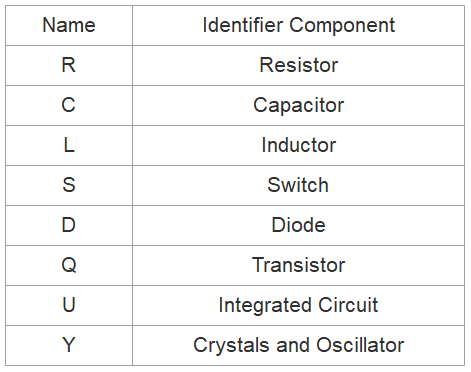
How to read electric engineering drawing and plumbing drawing electric engineering listen icon and plumbing engineering listen icon fraid proof engineering consultants. It is a device that stores electrical energy and usually has. To day ill show you video how to read electrical engineering drawing. In addition to the symbol each component on a schematic should have a unique name and value which further helps to identify it. Learn to read electrical and electronic circuit diagrams or schematics. They are usually represented by zig zag lines with.
In solidworks electrical complex schematics can be created in a matter of minutes and portions of the circuit copied and saved for re use. In electrical drawings every type of component and connection has its own specialized symboland every detail matters. Circuit or schematic diagrams consist of symbols representing physical components and lines representing wires or electrical conductors. Understand names and values. Scan over your schematics to figure out where your electrical currents are generated. To be able to read electrical as well as other types of drawings one must become familiar with the meaning of symbols lines and abbreviations used on the drawings and learn how to interpret the message conveyed by the drawings.
In general symbols should share a fair amount in common with the real life components they model. Answers are at the bottom and please dont peek.
