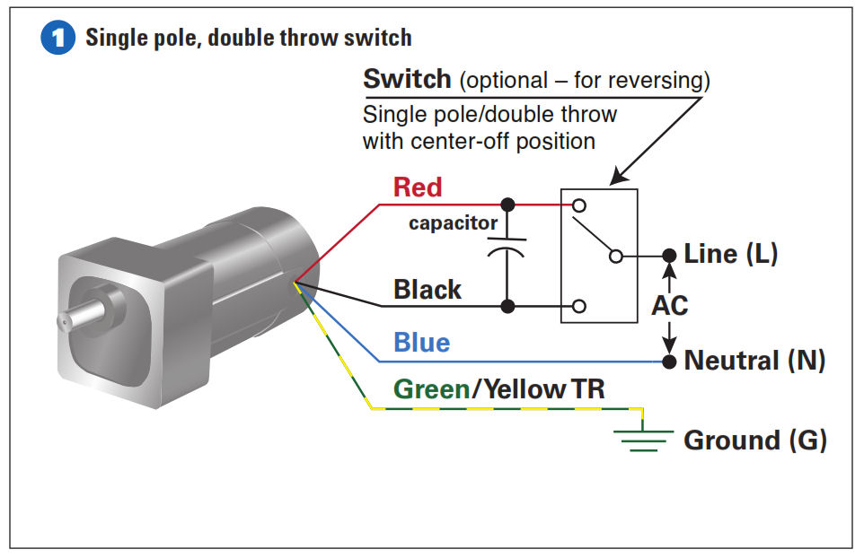
Ac80 ac90 ac100 single phase motors. Use figure 1 if your motor has a single voltage shunt field.

Ac Dc Motor Wiring Diagram Filter 10 Brillenstudio Weichert De
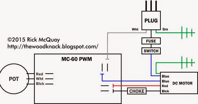
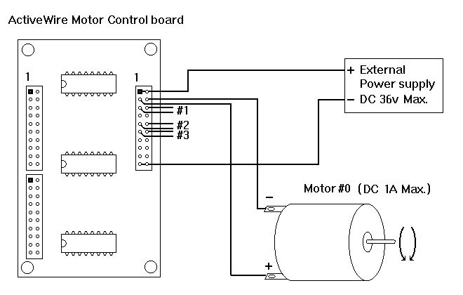
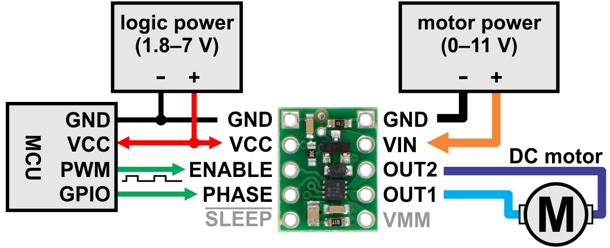
Dc motor wire diagram. For a given motor of fixed magnetic flux and number of windings the emf is proportional to the angular velocity of the rotor. As 183 wiring diagram with switch. Ac80 ac90 ac100 single phase motors. When voltage is applied current flows from power supply terminals through the series winding and armature winding. When you need to control a dc motor such as a dc linear actuator you usually need to be able to swap the polarity on the wires going to the motor. The emf tends to resist the rotation of the motor and is therefore referred to as back emf.
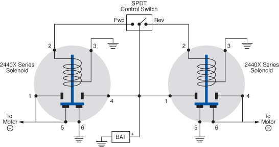
The three terminal input circuit of this dc motor direction control relay is connected to the dc control signal two of these terminals are used to control the forward and reverse rotation. A double pole double throw switch is used for this purpose but you have to wire it up correctly. Figure 2 illustrates the basic mechanism of a dc motor. Collection of dc motor wiring diagram 4 wire. How to wire dc reversible motor solid state relay dc bi directional motor direction controller wiring diagram. A sensorless bldc motor makes use of the electromotive force emf that gives rise to a current in the windings of any dc motor with a magnetic field that opposes the original change in magnetic flux as described by lenzs law.
If you mount magnets on a spinning shaft surrounded by the wire you have a motor in the diagram below the wire is arranged in two coils. It reveals the parts of the circuit as streamlined forms as well as the power and signal links between the gadgets. Wire a dpdt rocker switch for reversing polarity. Motor connections your motor will be internally connected according to one of the diagrams shown below. Wiring diagrams standard motors m 3ø wiring diagrams 1ø wiring diagrams m 3 m 3 high speed delta connection low speed star connection w2 or white w2 or white u2 or black u2 or black v2 or orange v2 or orange u1 or red u1 or red v1 or yellow v1 or yellow w1 or blue w1 or blue thermal contacts tb white thermal contacts tb white l1 l1 l2 l2 l3 l3 e e codes. Dc series motor circuit diagram in a series motor electric power is supplied between one end of the series field windings and one end of the armature.
A wiring diagram is a streamlined conventional pictorial representation of an electrical circuit. And upwards diagram dd5 two speed motors for all other single phase wiring diagrams refer to. As the magnets are alternately attracted to one coil and repulsed by the other it spins from one to the other and you get circular motion. 4 wire reversible psc motor. Home wiring diagrams brushless dc electric motor diagram 07 speed and torque values of motors for industrial power tools graph portescap 01 06 wasted current and current for torque in motors for industrial power tools straight spire portescap 01. These connections are in accordance with nema mg 1 and american standards publication 06.
Mgr dhk15a 200v series the dc reversible motor solid state relay is a dc forward and reverse switch for dc electric motor which uses the dc control signal to control the dc forward reverse motor.




.png)
