The basic control circuits include two wire three wire controls manual automatic sequential control stopstart forward reverse and jogging circuits. It is not difficult to learn the basic symbols.

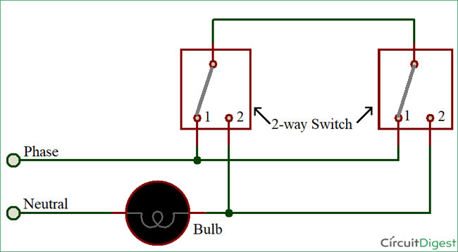
3 Way Light Switch Using A Two Wire Control Light Wiring
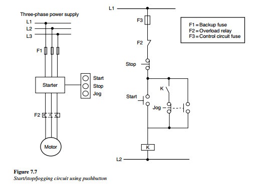
3 wire control diagram. Wiring diagrams show the connections to the controller. Two wire control as seen in configuration 1 consists of a control device containing one set of contacts used to facilitate the on an off operation of a pilot device. When push buttons control the operation of a motor three wires are run from the push button control station to the starter figure 18 6. Three phase electrical wiring installation in home iec nec. The typical elements in a wiring diagram are ground power supply wire as well as connection output tools switches resistors reasoning gateway lights etc. When you press the start button and the stop button is not pressed the 24vdc relay energizes and it pulls in the r1 contactor that feeds three phase power to the motor.
To read a wiring diagram initially you have to recognize just what essential aspects are consisted of in a wiring diagram and also which photographic icons are used to represent them. Multi speed 3 phase motor 3 speeds 1 direction power control diagrams one line diagram of simple contactor circuit. Here is the complete guide step by step. A very first appearance at a circuit diagram might be confusing yet if you can check out a subway map you can read schematics. Basic wiring for motor control technical data. Phase 2 l1 l2 l3 ground when used.
Wiring diagrams sometimes called main or construction diagrams show the actual connection points for the wires to the components and terminals of the controller. Once you do you are able to read diagrams quickly and can often understand a circuit at a glance. The more you work with both line and. Three wire control circuits are characterized by the use of momentary contact devices such as push buttons. 3 basic wiring for motor contol symbols standardized symbols make diagrams easier to read. Both line and wiring diagrams are a language of pictures.
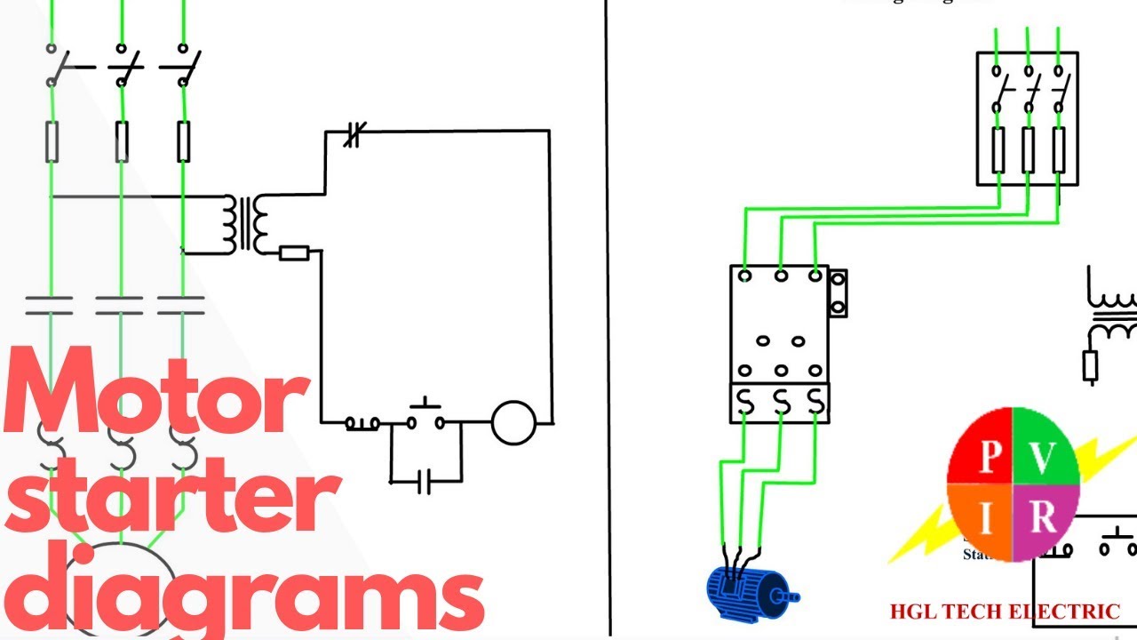
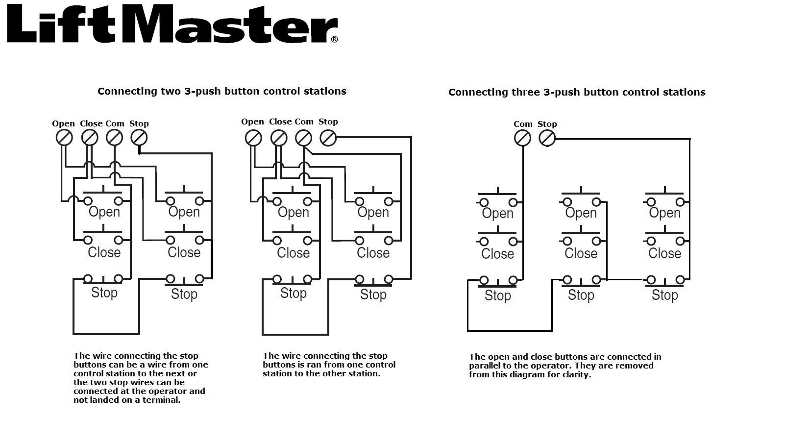
A simple three wire push button control circuit is shown in figure 18 7. The wiring connection of submersible pump control box is very simple. Three wire alternator wiring diagram a novice s overview of circuit diagrams. See image below for an example of 3 wire control being used to pull in a contactor to start a 3 phase motor. Phase 1 l2 l4. Single phase submersible pump control box wiring diagram 3 wire submersible pump wiring diagram in submersible pump control box we use a capacitor a resit able thermal overload and dpst switch double pole single throw.
Typical controller markings typical elementary diagram iec typical controller markings typical elementary diagram table 4 control and power connections for across the line starters 600 v or less from nema standard ics 2 321a60 1 phase 2 phase 4 wire 3 phase line markings l1 l2 l1 l3.
Gallery of 3 Wire Control Diagram